Two-wire electromagnetic flowmeter

a flowmeter and electromagnetic technology, applied in the field of electromagnetic flowmeters, can solve the problems of unstable flow measurement in the low flow rate region, low s/n ratio, and inability to execute stable flow measurement, and achieve the effect of increasing the stability of flow measuremen

Inactive Publication Date: 2005-02-08
YAMATAKE HONEYWELL CO LTD
View PDF4 Cites 10 Cited by
  • Summary
  • Abstract
  • Description
  • Claims
  • Application Information

AI Technical Summary

Benefits of technology

It is an object of the present invention to provide a two-wire electromagnetic flowmeter which can increase the value of the exciting current in a low flow rate region and increase the stability of flow measurement in the low flow rate region.

Problems solved by technology

That is, since the ratio of noise contained in the signal electromotive force becomes high as the flow rate increases, the S / N ratio becomes low, and stable flow measurement cannot be executed.
Flow measurement becomes unstable in the low flow rate region.
Hence, the signal electromotive force obtained by the signal electromotive force detection circuit 6-1 is small, and flow measurement is unstable.

Method used


Image

  • Two-wire electromagnetic flowmeter
  • Two-wire electromagnetic flowmeter
  • Two-wire electromagnetic flowmeter

Examples


Embodiment Construction

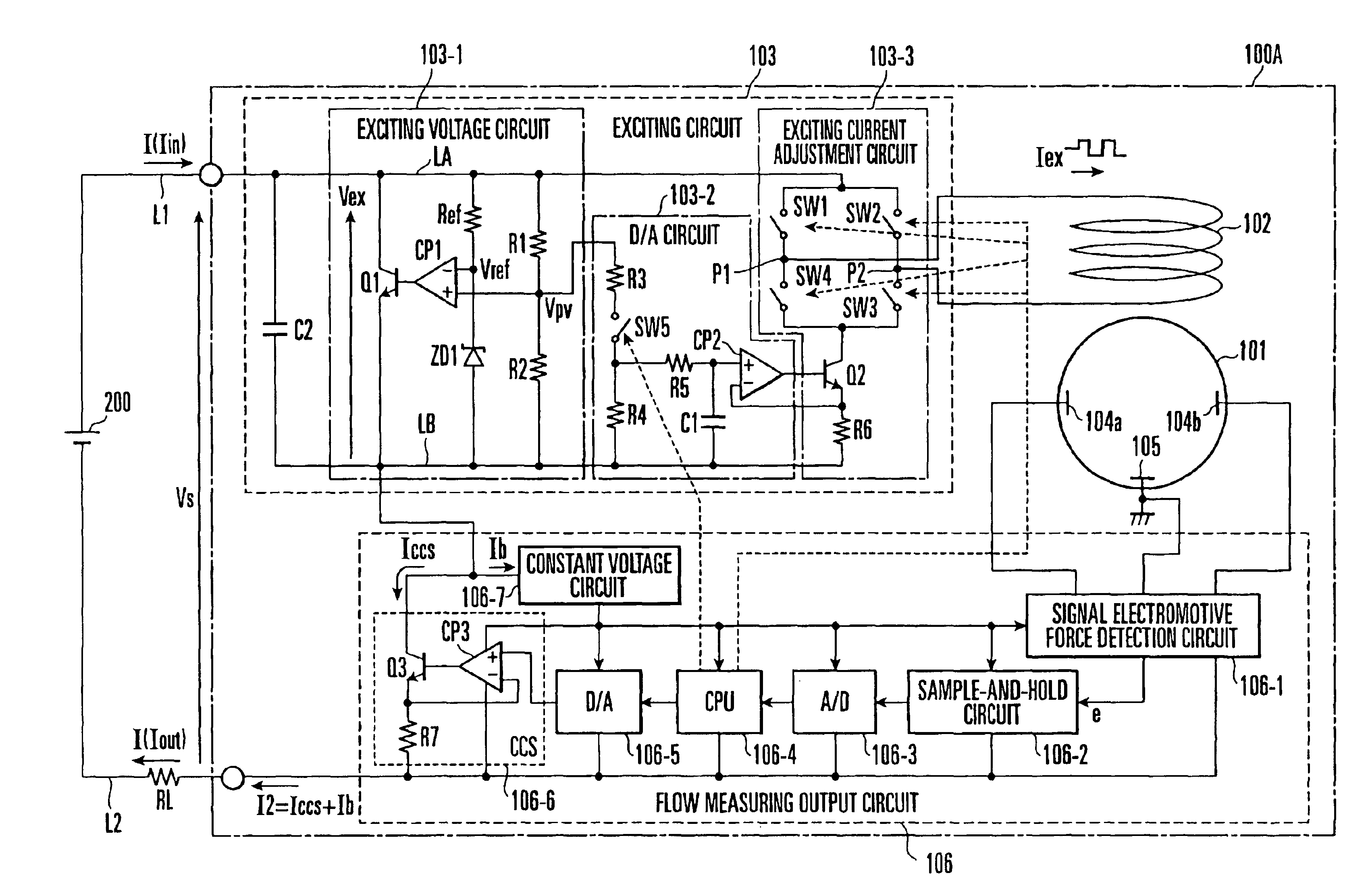
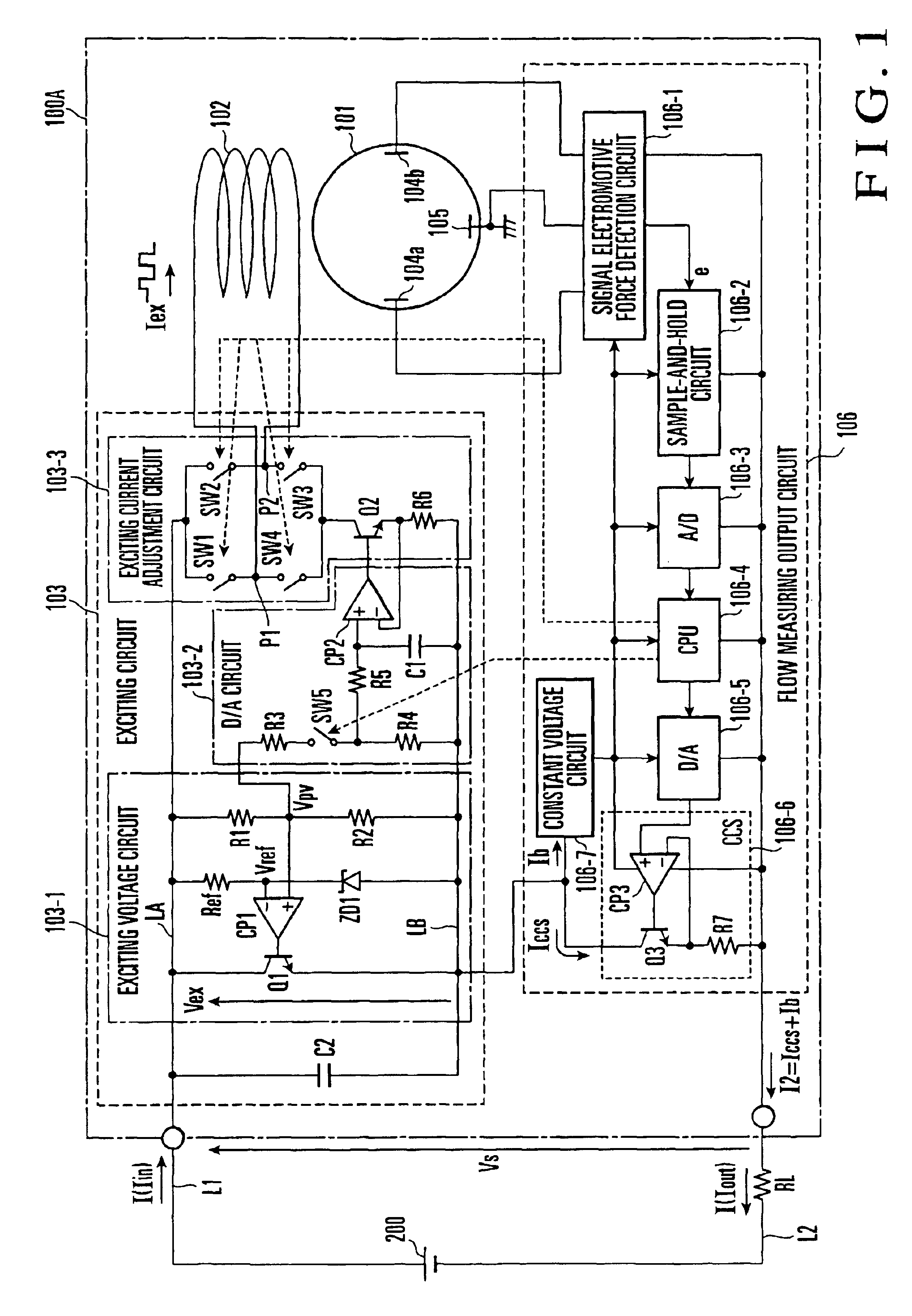
FIG. 1 shows a two-wire electromagnetic flowmeter according to an embodiment of the present invention. Referring to FIG. 1, an external voltage Vs from a DC power supply 200 is supplied to a two-wire electromagnetic flowmeter 100A according to this embodiment through a pair of power supply lines L1 and L2. An external load RL (resistance: 250 Ω) is connected to the power supply line L2 (DC 24 V). In this case, the value of the external voltage Vs supplied to the two-wire electromagnetic flowmeter 100A is obtained by subtracting the voltage drop at the external load RL from the power supply voltage of the DC power supply 200.

The two-wire electromagnetic flowmeter 100A is constituted by an exciting coil 102 which is arranged such that the generation direction of a magnetic field becomes perpendicular to the flowing direction of a fluid that flows through a measurement tube 101, an exciting circuit 103 which generates an exciting voltage Vex between a first line LA and a second line LB...


PUM


Abstract

In a two-wire electromagnetic flowmeter, an exciting coil generates a magnetic field in a direction perpendicular to the flowing direction of a fluid that flows through a measurement tube. A flow measuring output circuit adjusts an output current that flows to a pair of power supply lines to which an external power is supplied, in accordance with a flow measurement value obtained on the basis of a signal electromotive force which is generated in a direction perpendicular to the flowing direction of the fluid that flows through the measurement tube and the direction of the magnetic field generated from the exciting coil. An exciting circuit is connected in series with the flow measuring output circuit between the pair of power supply lines and supplies part of the output current to the exciting coil as an exciting current. In the exciting circuit, an exciting voltage circuit generates an exciting voltage between first and second lines. An exciting current adjustment circuit adjusts the value of the exciting current in accordance with the magnitude of the output current adjusted by the flow measuring output circuit. A capacitor is connected in parallel with the exciting voltage circuit between the first and second lines.

Description

BACKGROUND OF THE INVENTIONThe present invention relates to an electromagnetic flowmeter which measures the flow rate of a fluid having a conductivity in various process systems and, more particularly, to a two-wire electromagnetic flowmeter which outputs a measurement value by adjusting an output current flowing to a pair of power supply lines that supply an external voltage from a DC power supply.In a conventional two-wire electromagnetic flowmeter, an exciting coil is arranged such that the generation direction of a magnetic field becomes perpendicular to the flowing direction of a fluid that flows through a measurement tube. When a rectangular-wave-shaped exciting current Iex having a predetermined frequency is supplied to the exciting coil, a signal electromotive force (a signal proportional to the flow rate) is detected, which is obtained, in accordance with the Faraday's law, between electrodes that are arranged in the measurement tube to be perpendicular to the magnetic fiel...

Claims


Application Information

Patent Timeline
Patent Type & Authority Patents(United States)
IPC IPC(8): G01F1/56G01F1/60
CPCG01F1/60
Inventor MITSUTAKE, ICHIRO
Owner YAMATAKE HONEYWELL CO LTD
Why Eureka
Try Eureka