Dynamic desiccation cooling system for ships

Inactive Publication Date: 2005-02-15
CHIEF OF NAVAL RES OFFICE OF COUNSEL DEPT OF COUNSEL
View PDF7 Cites 66 Cited by
  • Summary
  • Abstract
  • Description
  • Claims
  • Application Information

AI Technical Summary

Benefits of technology

Optionally, the method could be implemented in a land based installation where a sufficient waste-heat source is collocated with an HVAC system for a building. AHC based on dynamic-desiccant technologies in accordance with the present invention could realize significant benefits in energy reduction and health and comfort for personnel in conditioned spaces.

Problems solved by technology

The system passes supply air through a desiccant wheel, which dries and concomitantly heats the supply air.

Method used


Image

  • Dynamic desiccation cooling system for ships
  • Dynamic desiccation cooling system for ships
  • Dynamic desiccation cooling system for ships

Examples


Embodiment Construction

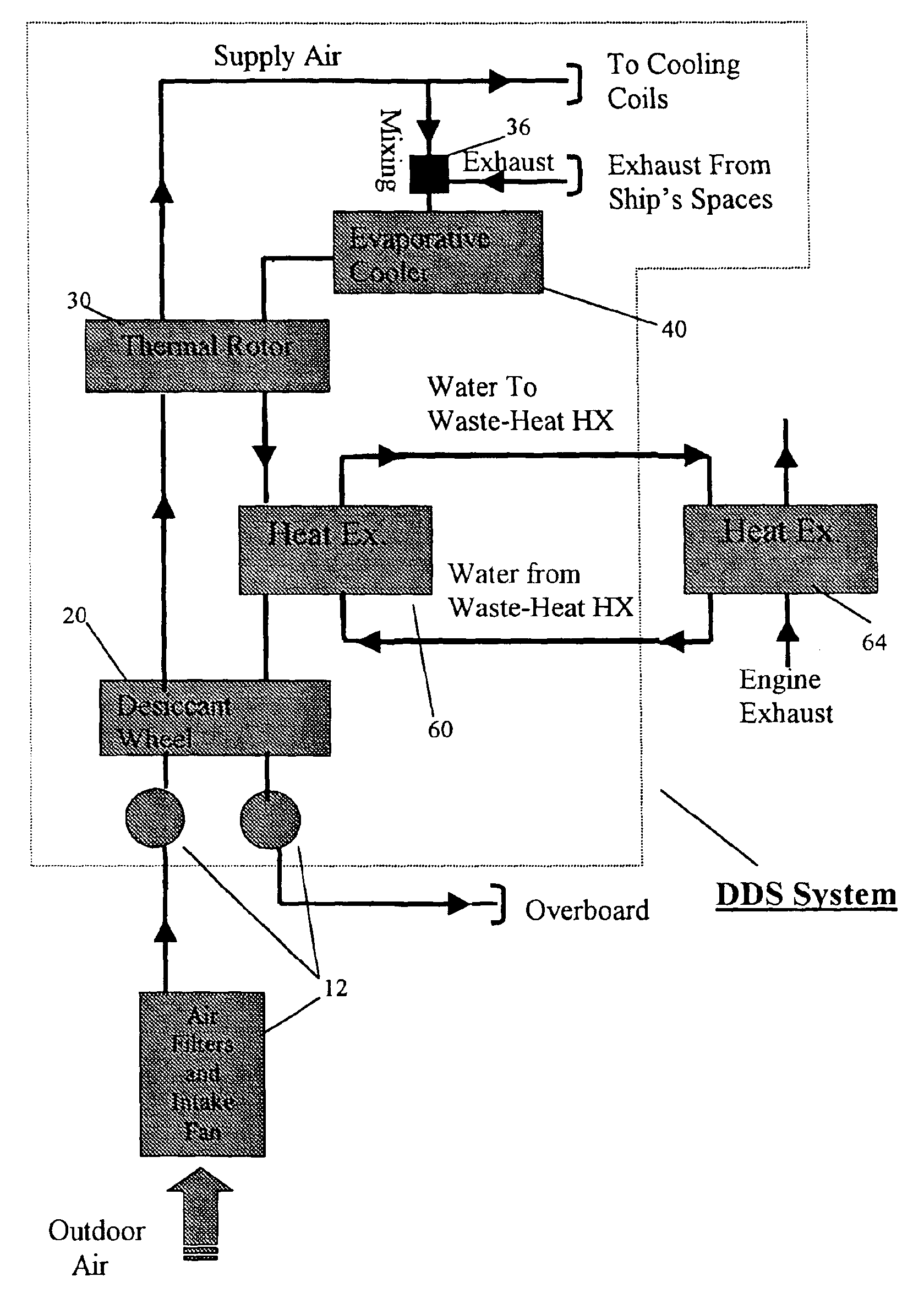
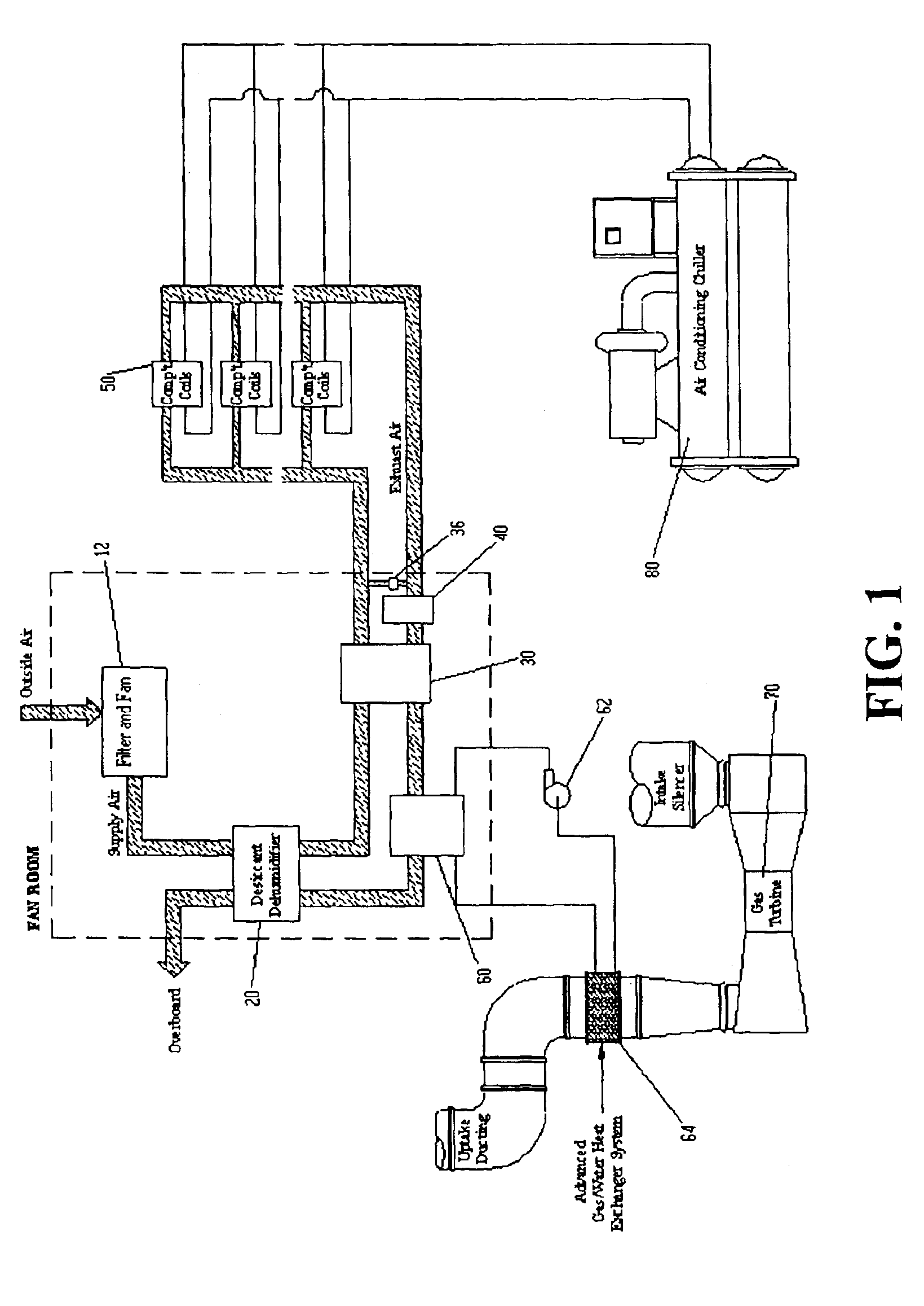
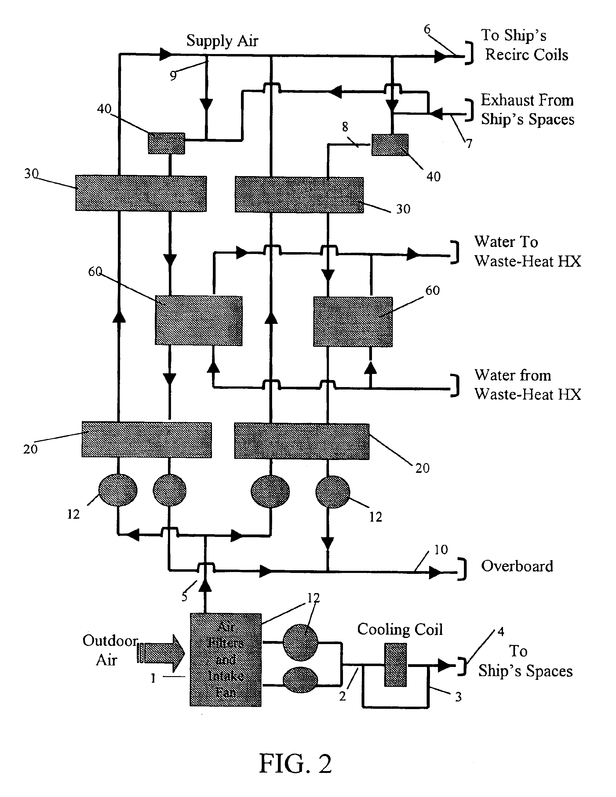
Referring to FIG. 1, a general schematic of the HVAC system on board a ship illustrates the method and apparatus for dehumidifying outside air prior to delivery to the compartment cooling coils 50, in accordance with the present invention. On the supply side, outside air is drawn through a series of filters and fans 12 and then passed through a desiccant wheel 20, which removes moisture from the outside air stream to lower the humidity of the outside air to a predetermined target value. This dry supply air is then cooled by a thermal rotor 30 and then sent to the various compartment cooling coils 50 (similar units are understood to have the same identifying numbers that are left out of the drawing for clarity). The compartment cooling coils 50 are fed chilled water from the AC plant chiller 80 to cool and dehumidify the supply air received from the fan room. The compartment cooling coils 50 are designed to deliver the supply air at the correct temperature and humidity needed to hand...


PUM


Abstract

The present invention describes methods and apparatus for controlling the humidity of air supplied to cooling coils on a gas turbine powered ship through a dynamic desiccation system. The system passes supply air through a desiccant wheel, which dries and concomitantly heats the supply air. This supply air stream is then passed through a rotatable thermal wheel, wherein heat is transferred from the dry supply air to an exhaust-air mixture, thereby conditioning the supply air for delivery and circulation to a plurality of cooling-coil units in a plurality of compartments. The exhaust air from the compartments is first mixed with some of the treated supply air to lower the absolute humidity to a value needed for effective regeneration of the desiccant wheel. An evaporative cooler then conditions the exhaust-air mixture for effective cooling of the supply air in the thermal rotor, which also serves as an air preheater for desiccant regeneration. The exhaust-air mixture is then heated to the desiccant regeneration temperature by passing the preheated exhaust air through a heat exchanger supplied with gas-turbine waste heat. After this heated exhaust-air mixture regenerates the desiccant wheel by fully drying out the desiccant on the wheel, it is expelled from the fan room.

Description

BACKGROUND OF INVENTIONThe commercial building business continues to place a strong focus on Active Humidity Control (AHC) equipment for commercial air conditioning (AC) applications. This has grown out of an understanding that for building applications, the independent control of humidity and temperature afforded by AHC offers marked advantages over the traditional “cool first” approach. AHC conserves energy while affording building occupants immediate and lasting improvements in comfort, health and indoor-air quality. However, such AHC is not presently used in ships, though ships could also benefit from such systems.Current AC systems aboard ship use the traditional “cool first” approach, in which the air in the ship's compartments is simultaneously dehumidified and cooled to prescribed environmental conditions. The demand on the cooling system is especially acute in a hot and humid marine environment where moisture levels in the compartment replenishment air delivered to the AC s...

Claims


Application Information

Patent Timeline
Patent Type & Authority Patents(United States)
IPC IPC(8): B63H21/00B63H21/16F24F3/14F24F3/12
CPCB63H21/16F24F3/1423F24F2203/1032F24F2203/1084F24F2203/1056F24F2203/1072F24F2203/1076F24F2203/104F05D2260/608
Inventor DIGIOVANNI, ANTHONY J.COLAHAN, DENIS J.KNAUSS, DONALD T.
Owner CHIEF OF NAVAL RES OFFICE OF COUNSEL DEPT OF COUNSEL
Why Eureka
Try Eureka