Method of manufacturing glass gobs molded glass articles, and optical elements

a technology of glass gobs and glass pieces, which is applied in the direction of blowing machines, manufacturing tools, instruments, etc., can solve the problems of glass distortion after glass melt supply and failure to work well with the receiving molds

Inactive Publication Date: 2005-02-15
HOYA CORP
View PDF13 Cites 6 Cited by
  • Summary
  • Abstract
  • Description
  • Claims
  • Application Information

AI Technical Summary

Problems solved by technology

Although the above-mentioned method of molding glass gobs is a manufacturing method affording good production efficiency, the following technical background and problems exist.
(1) Since the glass melt is continuously discharged through a flow nozzle, the supplying (referred to hereinafter as “casting”) of glass melt to the receiving molds does not work well when time is required to switch out the receiving molds.
However, when the amount of deformation is significant, distortion remains in the glass after it returns its original shape.
This distortion remains in the molded glass gob and in the glass preform employed for press-molding, becoming a defect in the press-molded product.
However, when this time is excessively short, the glass gob is taken out before it has adequately cooled, that is, while it is still deformable.
When this happens, the glass gob is deformed during takeout or during delivery process after takeout, the glass gobs stick to each other, and defective product is obtained.
Thus, in methods in which a continuously flowing glass melt is sequentially received by multiple receiving molds and molded into glass gobs by the receiving molds while still at a temperature range at which the glass melt is deformable, the above-described technical background and problems exist.
However, when comparatively large glass gobs are produced, or even when comparatively small glass gobs are produced at rapid speed (with better production efficiency), it is difficult to manufacture a good product.

Method used


Image

  • Method of manufacturing glass gobs molded glass articles, and optical elements
  • Method of manufacturing glass gobs molded glass articles, and optical elements
  • Method of manufacturing glass gobs molded glass articles, and optical elements

Examples


examples 1-5

, Comparative Example 1-5

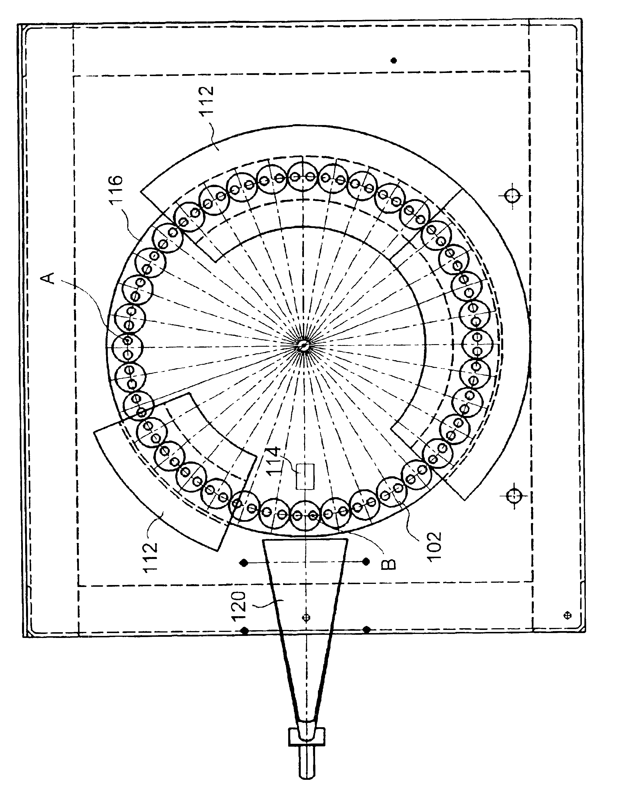
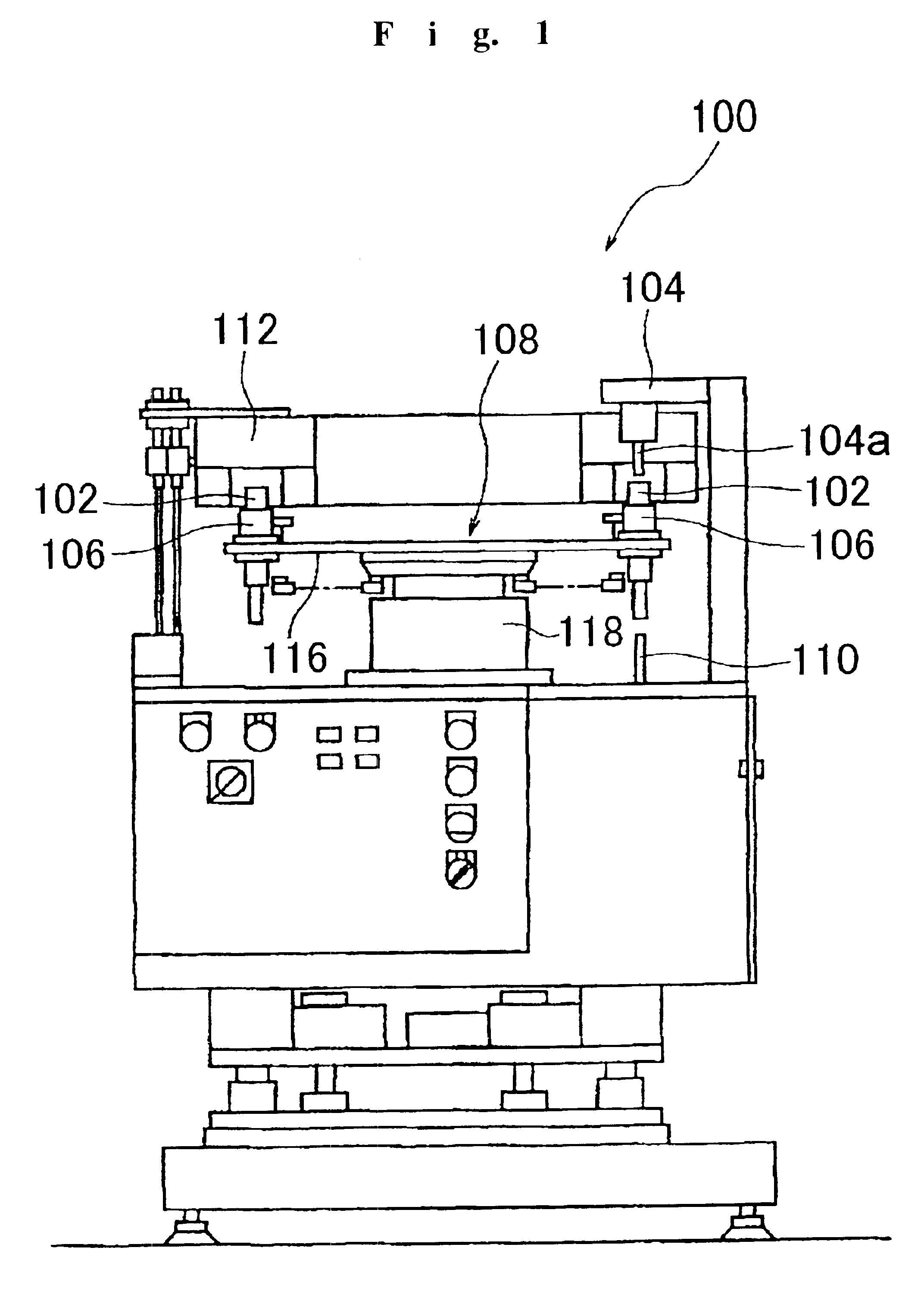
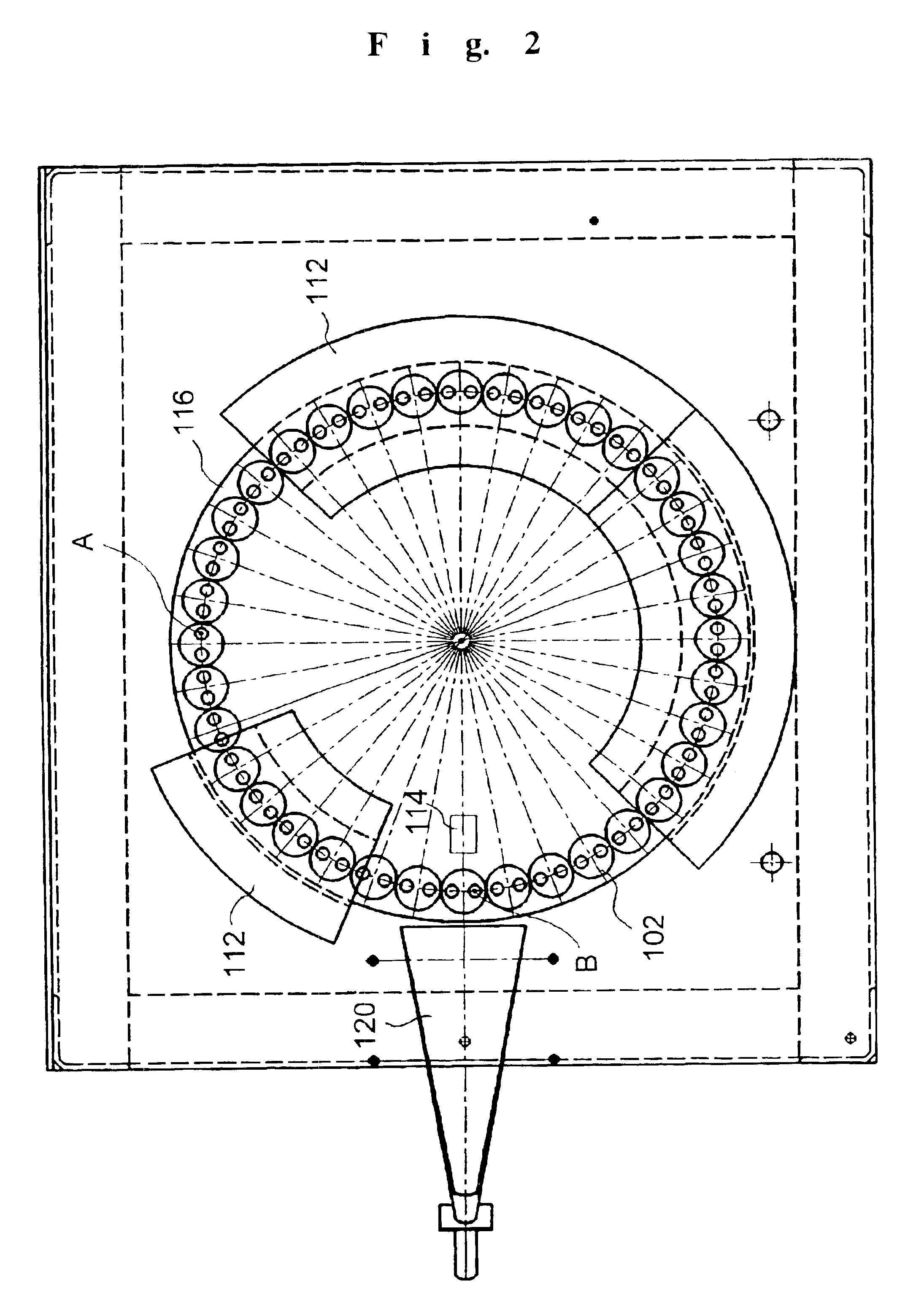
Glass melts of both B2O3—ZnO—La2O3 and SiO2—TiO2 optical glasses were prepared. In air, these glass melts were made to continuously flow from platinum-alloy flow nozzles, the glass melts were sequentially received by glass gob molding parts positioned on the upper surface of glass gob molding molds made of carbon, and the glass melts were floated and molded to obtain glass gobs. The viscosity of the glass melts during flowing was 10 poise for the B2O3—ZnO—La2O3 optical glass and 5 poise for the SiO2—TiO2 optical glass. The glass glob molding device shown in FIG. 1 was employed in Examples 1 and 2.

In Example 1, glass gobs were molded from a glass melt obtained from B2O3—ZnO—La2O3 optical glass, and in Example 2, glass gobs were molded from a glass melt obtained from SiO2—TiO2 optical glass. In Examples 1 and 2, 36 glass gob molding molds each equipped on its upper surface with two glass gob molding parts were employed, yielding a total number of glass gob mol...

example 6

The glass gobs obtained in Examples 1-5 were further annealed in air and then cooled to room temperature. The glass gobs were then barrel polished to uniformly roughen the surfaces and employed as preforms for press-molding. The preforms for press-molding were uniformly coated with a boron nitride powder mold releasing agent, heated in air to within a temperature range yielding a glass viscosity of 104-106 poise, and employed in press-molding using a metal mold made of an super-hard alloy, yielding the desired final product in the form of a lens blank approximating the shape of a meniscus lens. This lens blank was then ground and polished to finish a meniscus lens.

Through suitable selection of the shape of the molding surface of the metal mold, it is possible to press-mold the blanks of other lenses, as well as the blanks of optical elements such as prisms other than lenses. These blanks can then be ground and polished to obtain final products.

It is also possible to form thin optica...

example 7

A glass melt yielding optical glass with a yield point of not more than 600° C. was prepared and glass gobs were molded using the glass gob molding device of Example 1. The glass gobs obtained were annealed and cooled to room temperature. All processing up to this point was conducted in air. Next, in a nitrogen atmosphere, the glass gobs were heated to a temperature yielding a glass viscosity of about 108 poise and the heat-softened glass was precision press-molded in a nitrogen atmosphere using a press-molding mold to precisely transfer the molding surface of the press-molding mold to the glass. Aspherical lenses were obtained by this method. By such a precision press-molding, optical elements such as aspherical lenses without grinding and polishing steps following press-molding.

Thin optical films can be formed as necessary on the optical elements obtained.

The present invention as set forth above provides a method of manufacturing glass gobs with high productivity without defects i...


PUM

PropertyMeasurementUnit
radiusaaaaaaaaaa
radiusaaaaaaaaaa
viscosityaaaaaaaaaa

Abstract

Methods and a device of manufacturing glass gobs with good productivity without defects in appearance from a glass melt. Glass gobs are manufactured from glass melt gobs by molding and cooling glass melt gobs in glass gob molding parts that are intermittently rotated. In one method, single intermittent rotation period of said glass gob molding part is in a range of 0.1 to 0.25 second, and the single intermittent rotation distance of said glass gob molding part is 0.8-7 cm. The device for molding glass gobs from a continuously flowing glass melt has a turntable intermittently rotated around a rotation axis and glass gob molding molds positioned on said turntable. The glass gob molding mold has multiple glass gob molding parts that receive glass melt on the upper surface thereof and mold the glass melt into glass gobs. The glass gob molding mold is positioned on a turntable so that said glass gob molding parts are disposed at equal intervals around a circumference centered on the rotation axis of the turntable.

Description

TECHNICAL FIELDThe present invention relates to a method of, and device for, manufacturing glass gobs that are suitable preforms for use in press-molding from a glass melt; a method of manufacturing molded glass articles employing such glass gobs as press-molding preforms in which the preform is heated and press-molded; and a method of manufacturing optical elements by grinding and polishing the molded glass articles.TECHNICAL BACKGROUNDMethods of directly manufacturing high-precision molded glass articles such as lenses by heating a glass preform and molding it in a press to a prescribed shape and methods of manufacturing glass optical elements such as lenses by grinding and polishing molded products are widely employed as techniques permitting the mass production of high-precision glass products such as optical elements with high reproducibility and good production efficiency. In such press-molding methods, press-molding devices, molding conditions and the like vary widely dependi...

Claims


Application Information

Patent Timeline
Patent Type & Authority Patents(United States)
IPC IPC(8): C03B11/02G02B3/00C03B7/14C03B11/00
CPCC03B11/02
Inventor YOSHIKUNI, KEISUKETOUMA, YOUJIIGUCHI, YOSHINORI
Owner HOYA CORP
Why Eureka
Try Eureka