
Temperature, vapor space and fuel volatility-compensated evaporative emissions system leak test method

a technology of evaporative emissions system and temperature, which is applied in the direction of fluid tightness measurement, instruments, machines/engines, etc., can solve the problems of affecting the test, affecting the normal release of pressure, and prone to sudden changes in fuel vapor pressure of high-temperature or high-volatile fuel

Inactive Publication Date: 2005-02-15
STATE OF CALIFORNIA BUREAU OF AUTOMOTIVE REPAIR
View PDF9 Cites 18 Cited by
  • Summary
  • Abstract
  • Description
  • Claims
  • Application Information

AI Technical Summary

Problems solved by technology

A basic problem with all of the above inventions is that these tests do not consider all of the considerable variation in fuel temperature and volatility under which the vehicle is leak-tested, which can strongly influence the test results.
High-temperature or high-volatility fuel is prone to sudden changes in fuel vapor pressure due to the increased vaporization rate of the fuel; these changes can impair or mask entirely the ordinary release of pressure through a leak.
Thus, if the pass-fail decision cutpoint is not compensated for these variables, a problem arises: a vehicle with a given size leak may pass one test and fail another, due to differences in test conditions (irrespective of any repair).
Such an outcome is most unfavorable in a governmental regulatory environment, where such tests need to produce reliable, consistent outcomes.

Method used


Image

  • Temperature, vapor space and fuel volatility-compensated evaporative emissions system leak test method
  • Temperature, vapor space and fuel volatility-compensated evaporative emissions system leak test method

Examples


Embodiment Construction

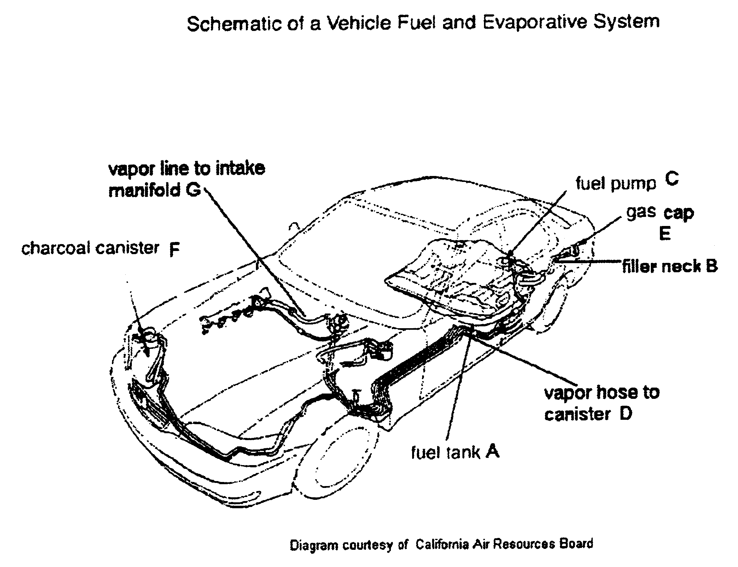
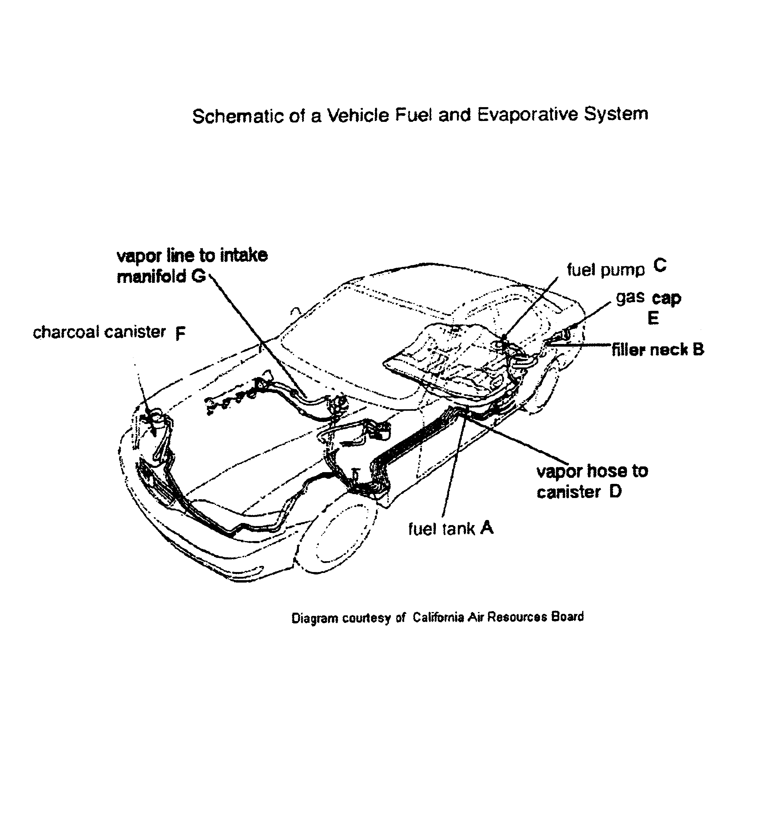
Attached in FIG. 1 is a schematic diagram of a vehicle fuel tank and associated evaporative emissions control system. The fuel tank (marked A) contains several openings, all ordinarily sealed: one at the fuel tank filler neck (B), one at the mounting housing for the fuel pump (C), one at the inlet to the vapor hose to the canister (D), and a rollover valve (not shown). Some vehicles may contain openings additional to these. The evaporative emissions control system is comprised of these seals, as well as several other components: the fuel cap (E), an elastomeric rubber connector from the filler neck (B) to the fuel tank (A), a charcoal canister (F), and a vapor hose (G) connecting the canister to the engine intake manifold. In general, the operation of the system is as follows: During vehicle operation, the fuel in fuel tank A is heated by the return of hot fuel from the engine and from ambient sources, such as hot pavement. This heating causes vapor generation in fuel tank A; this v...


PUM


Abstract

A method for the leak testing of a motor vehicle fuel tank and associated evaporative emissions control system is provided. Nitrogen, compressed air or other gases are used to pressurize the system. The time required for pressurization is used to determine the tank headspace volume. The system pressure is then monitored for 120 seconds. The pressure drop in this period is then compared with a pass-fail value cutpoint from a look-up table stored in a computer attached to the testing apparatus. A pass-fail determination is then made. The pass-fail value cutpoint is pre-determined for a specified vapor volume and estimated liquid fuel temperature, as well as time of year, so that systems with leaks larger than a specified diameter consistently fail the test, while systems with leaks smaller than this value consistently pass the test. The test pass-fail criterion is thus compensated for the conditions (tank fill level and fuel temperature, and seasonal variations in fuel volatility) experienced the actual test.

Description

BACKGROUND OF THE INVENTION1. Field of the InventionThe invention relates to the leak testing of automotive vehicle fuel tanks and associated evaporative emissions control systems. More particularly it relates to a method for testing such systems which corrects for a fundamental problem with previous methods: the lack of compensation for variations in the test conditions of liquid fuel temperature and volatility.2. Background InformationSeveral previous inventions have dealt with the problem of leak detection from automotive fuel tanks and associated evaporative emissions control systems. Rogers, in U.S. Pat. No. 5,369,984, described a method for “testing of tank integrity of vehicle fuel systems.” Fournier, in U.S. Pat. No. 5,425,266, detailed an apparatus and method for the “non-intrusive testing” of such systems, employing an annular device to produce a seal between a pressure control unit and the fuel tank filler neck into which the pressure control unit was inserted. Kammeraad ...

Claims


Application Information

Patent Timeline
Patent Type & Authority Patents(United States)
IPC IPC(8): G01M3/02
CPCG01M3/025
Inventor AMLIN, DAVID J.
Owner STATE OF CALIFORNIA BUREAU OF AUTOMOTIVE REPAIR
Learn More