Measurement apparatus for measuring physical quantity such as fluid flow

Inactive Publication Date: 2005-02-15
HITACHI LTD +1
View PDF8 Cites 8 Cited by
  • Summary
  • Abstract
  • Description
  • Claims
  • Application Information

AI Technical Summary

Benefits of technology

An objective of the present invention is to prevent the deterioration in the detection accuracy b

Problems solved by technology

However, although the resin can prevent the temperature of the above sensors from increasing due to the heat conduction, it is not possible to completely prevent the temperature of the above sensors from increasing because the sensors receive the radiation heat from the internal wall of the intake-air passage.
However, as described above, since the thermal conductiv

Method used


Image

  • Measurement apparatus for measuring physical quantity such as fluid flow
  • Measurement apparatus for measuring physical quantity such as fluid flow
  • Measurement apparatus for measuring physical quantity such as fluid flow

Examples


Embodiment Construction

Hereafter, details of the embodiments will be explained with reference to the drawings.

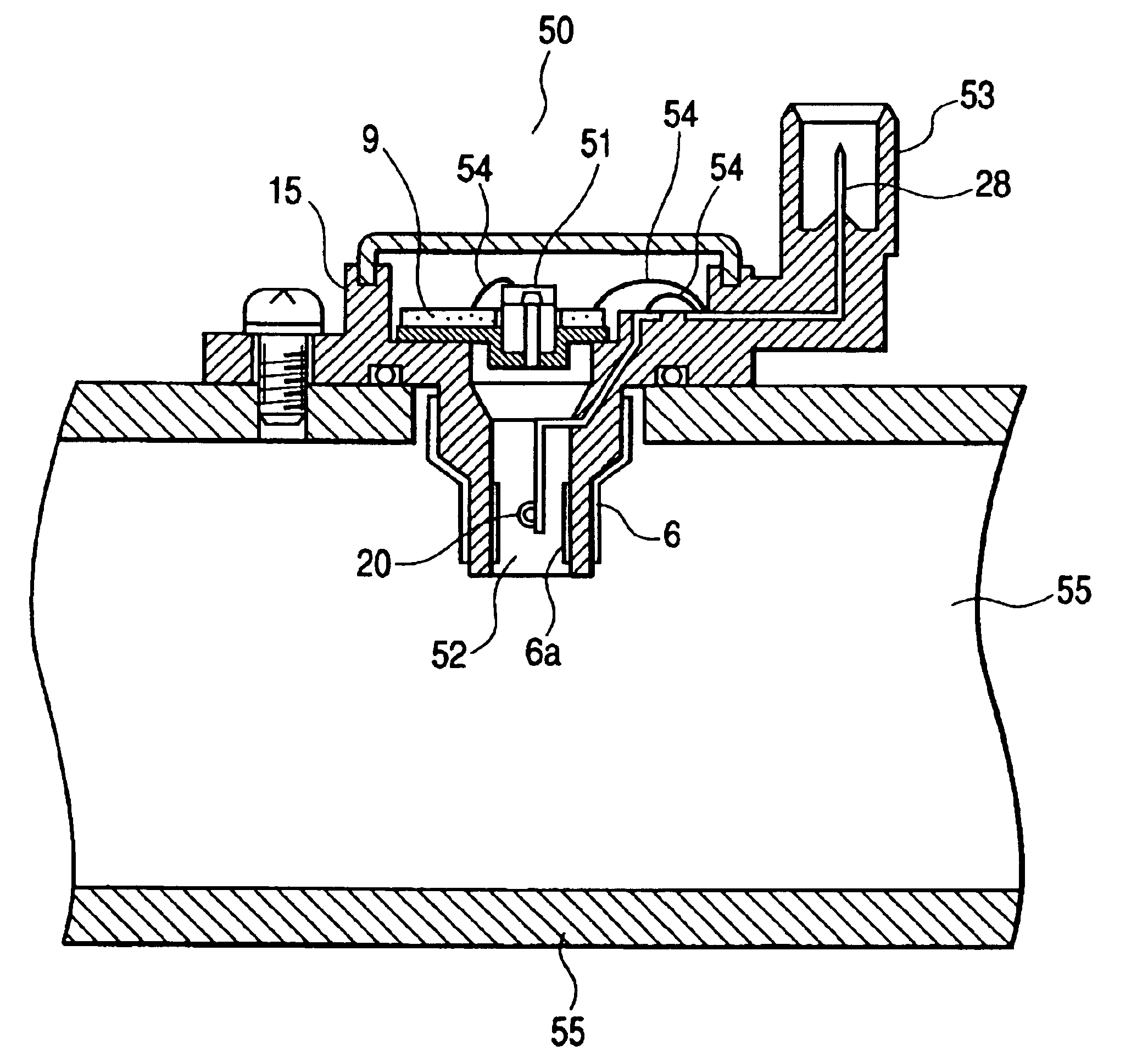
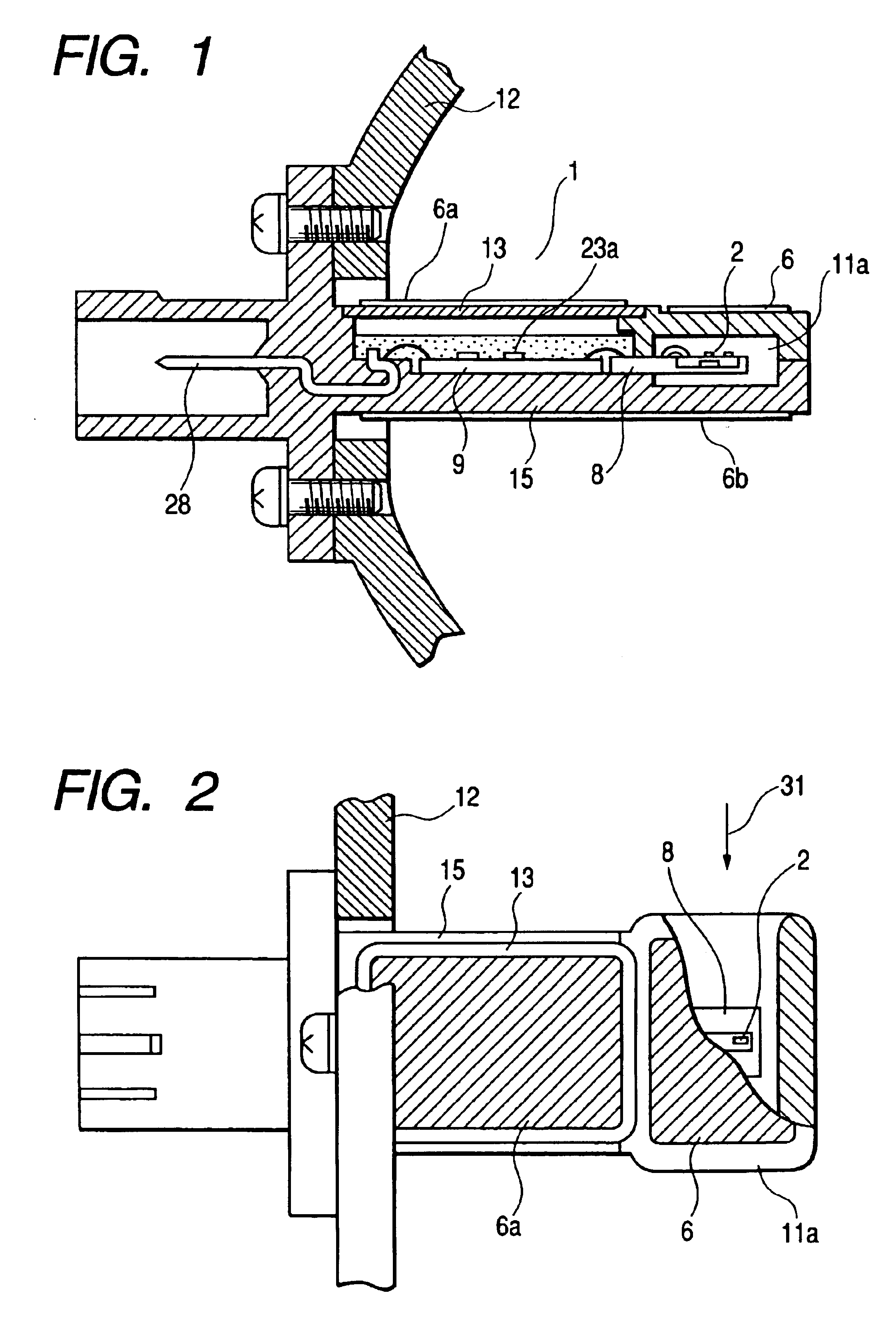
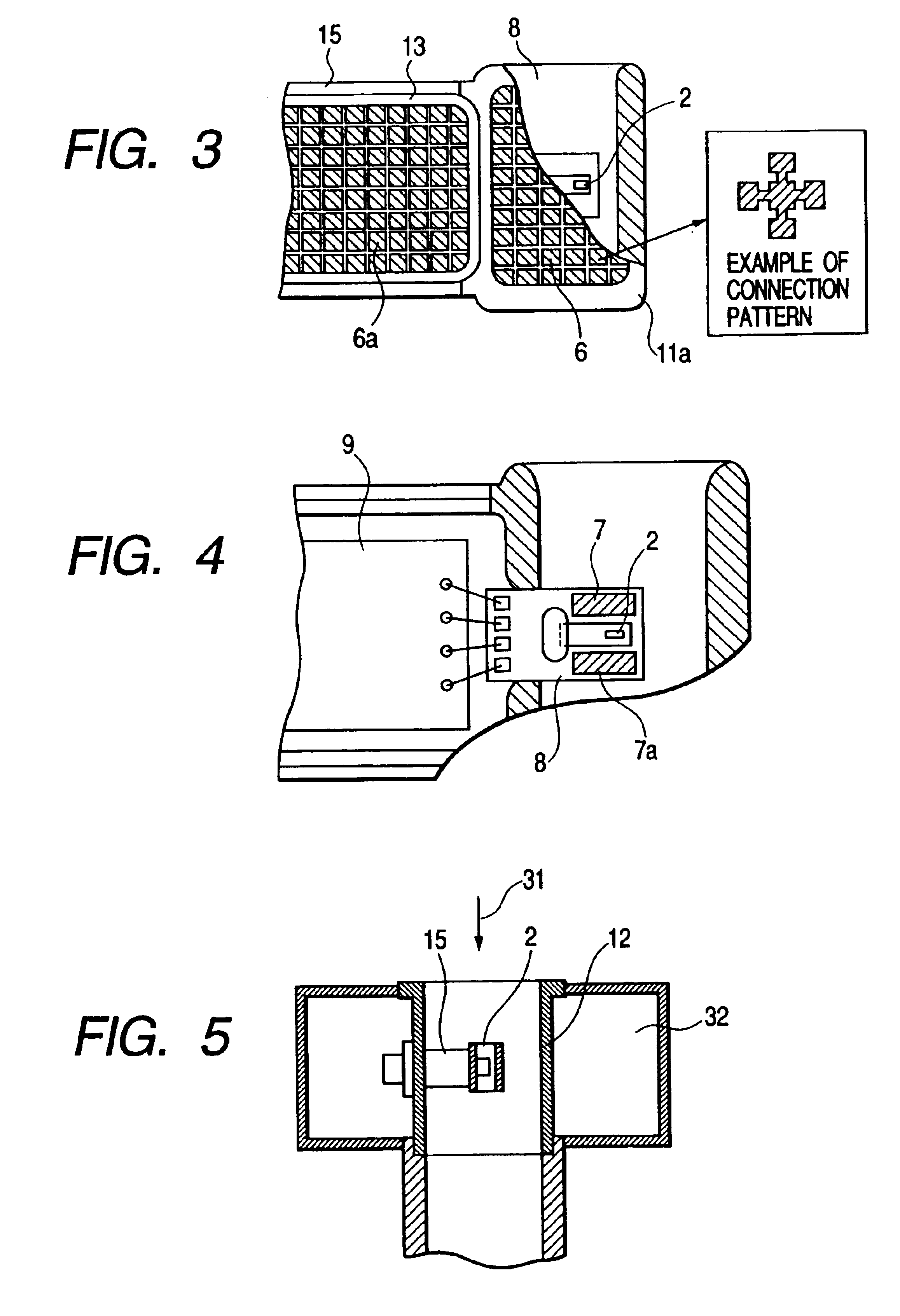
FIG. 1 shows a cross sectional view of the structure of a thermal type air flow sensor of the first embodiment according to the present invention. Further, FIG. 2 shows a plan view of the structure of the thermal type air flow sensor shown in FIG. 1. As shown in FIG. 1 and FIG. 2, the thermal type air flow sensor 11 includes a semiconductor sensor element 2, a substrate8 for supporting the semiconductor sensor element 2, an auxiliary air passage 11a, metal terminals 28 for outputting signals to and inputting signals from an external circuit, etc. The air flow direction is shown by arrow 31 in FIG. 2. Further, a diaphragm composed of an electrical insulating film is formed in the back surface part of a semiconductor substrate by an anisotropic etching method, and the semiconductor sensor element 11a which includes a heating resistor 3 formed on the diaphragm, and a temperature sensitive resistor 4 ...


PUM


Abstract

Resin members, on the surfaces of which metal films are formed, are used for; an auxiliary air passage provided in a main air passage, in which a sensor element of a physical quantity sensor such as an air flow sensor, an intake-air temperature sensor, etc., is situated; a housing; and so forth; in order to decrease both the thermal conductivity and the emissivity of those components to respective small values, whereby the temperature increase of the sensor due to both the heat conduction and the heat radiation can be suppressed.

Description

BACKGROUND OF THE INVENTIONThe present invention relates to a measurement apparatus for measuring a physical quantity such as fluid flow, pressure, temperature, O2 concentration, etc., and especially to an air flow-measurement apparatus for measuring the flow rate of air taken into an internal combustion engine.A thermal type flowmeter has been a mainstream of an air flow sensor, which is located in an intake-air passage in an internal combustion engine of a vehicle such as a car, because this type air flow sensor can directly detect a mass flow rate of air.In the technique of the above thermal type air flow sensor, an auxiliary air passage is formed in an intake-air passage, and a heating resistor element and a temperature sensitive resistor element are situated in the auxiliary air passage as disclosed in Japanese Patent Application Hei 8-338745. Further, by providing radiation fins at the side face of the auxiliary air passage, the temperature of the air flow sensor is prevented ...

Claims


Application Information

Patent Timeline
IPC IPC(8): G01F1/684G01F5/00
CPCG01F1/684G01F5/00G01F1/6845G01F1/6842
Inventor WATANABE, IZUMISAITO, NAOKIKOZAWA, MASAYUKINAKADA, KEIICHIUEYAMA, KEI
Owner HITACHI LTD
Why Eureka
Try Eureka