Vehicle air conditioning system with cold accumulator
a technology of air conditioner and accumulator, which is applied in the direction of domestic cooling equipment, lighting and heating equipment, instruments, etc., can solve the problems of increasing costs, and achieve the effect of simple structure and stable operation
- Summary
- Abstract
- Description
- Claims
- Application Information
AI Technical Summary
Benefits of technology
Problems solved by technology
Method used
Image

Examples
first embodiment
(First Embodiment)
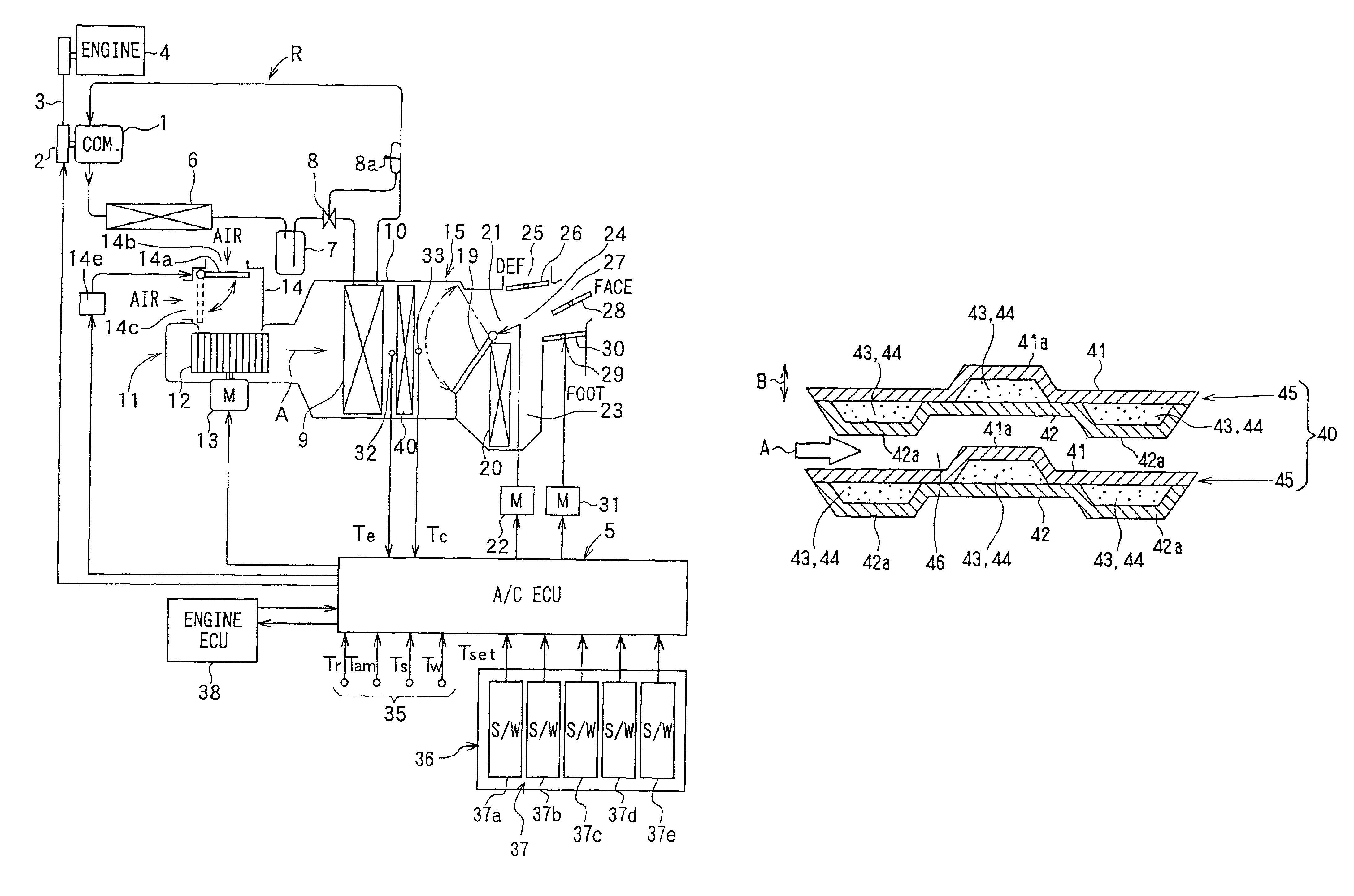
FIG. 1 is a view illustrating an entire constitution of a first embodiment. A refrigerating cycle R of an air conditioning system for a vehicle has a compressor 1 for sucking, compressing, and discharging a refrigerant, and the compressor 1 is provided with an electromagnetic clutch 2 for intermittent power. Since the power from a vehicular engine 4 is transmitted to the compressor 1 via the electromagnetic clutch 2 and a belt 3, an operation of the compressor 1 is intermittent according to an intermittent current carried to the electromagnetic clutch 2 by an air-conditioning electronic control unit (ECU) 5.
A super-heated gas refrigerant having a high temperature and a high pressure, discharged from the compressor 1, flows into a condenser 6, and is heat-exchanged with outside air blown by a cooling fan (not illustrated) to be cooled and condensed. The refrigerant condensed in the condenser 6, next, flows into a receiver 7, gas and liquid of the refrigerant are sep...
second embodiment
(Second Embodiment)
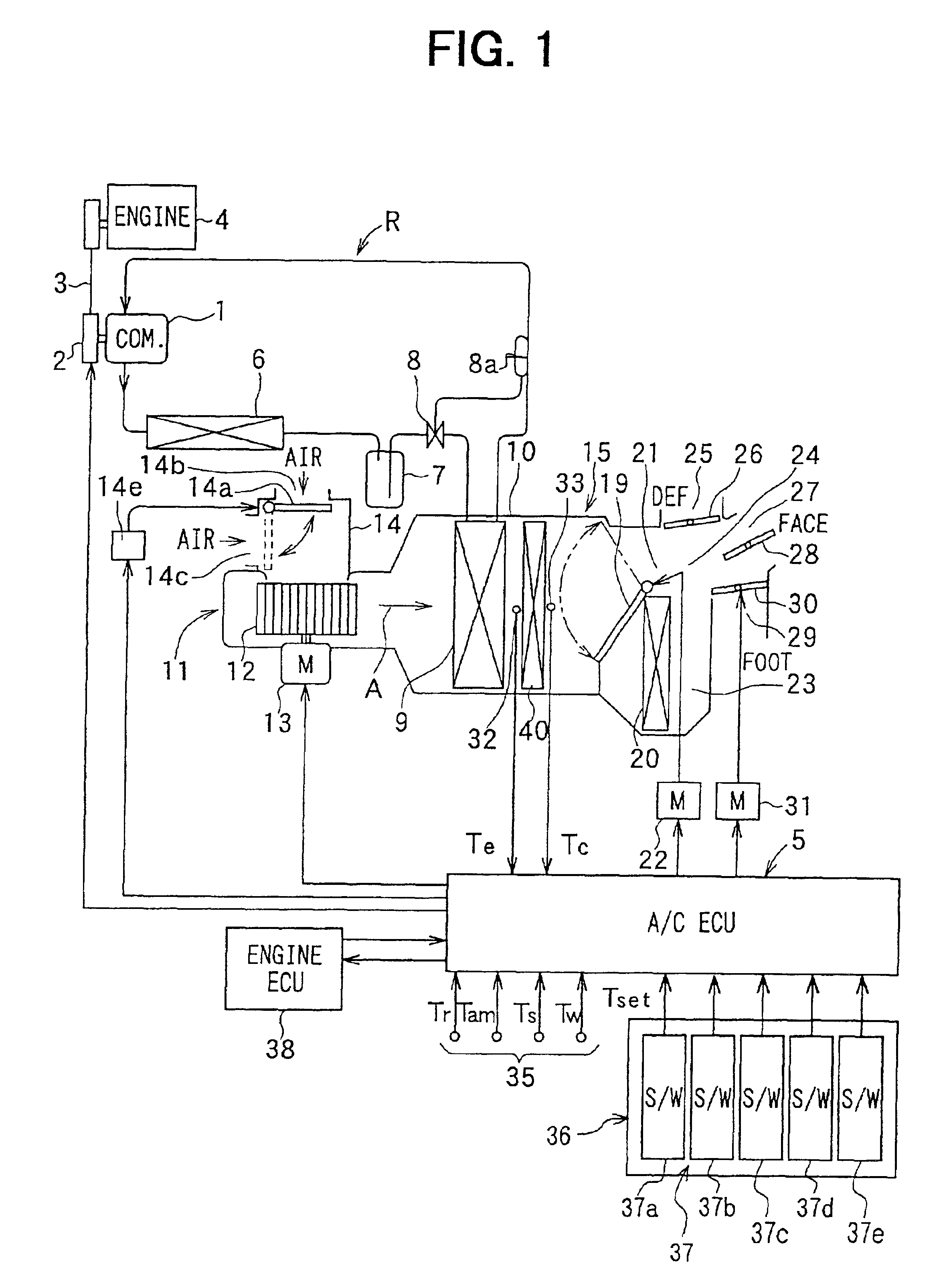
In the above-described first embodiment, the cold accumulator 40 is constituted by a finless structure. However, in the second embodiment, as illustrated in FIG. 3, a cold accumulator 40 is constituted to have a fin and tube type heat-exchanging structure.
As shown in FIG. 3, two pieces of heat transfer plates 410 and 420 are molded into a shape swelled out in a bowl shape respectively to an outward direction. By bonding the two pieces of the heat transfer plates 410 and 420 in a hollow shape, a tube 430 can be formed. Further, corrugate type fins 440 folded and bent in a wave shape and the tubes 430 are alternately stacked on each other in the vertical direction in FIG. 3. The portions between the heat transfer plates 410 and 420 of each tube 430 and the portions between each fin 440 and each tube 430 are bonded with each other by brazing of aluminum. After the brazing, the cold accumulating material 44 is filled and hermetically sealed in an inner section space o...
third embodiment
(Third Embodiment)
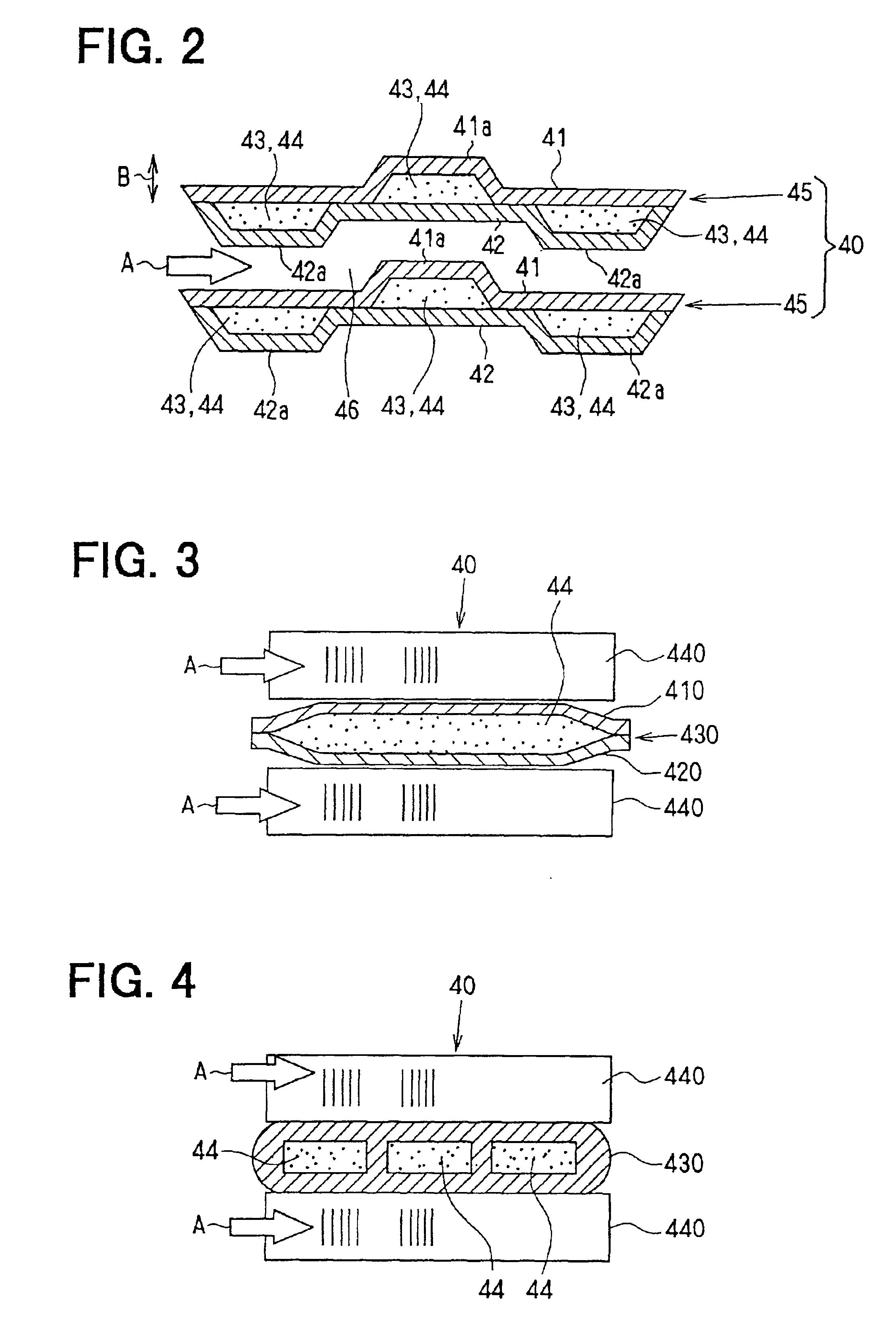
In the second embodiment described above, the tube 430 is constituted by bonding the heat transfer plates 410 and 420 composed of a press molded thin plate material. However, in the third embodiment, as illustrated in FIG. 4, a tube 430 is formed by an extrusion to have a sectional shape of a porous form, and the extruded tubes 430 and the corrugate type fins 440 are bonded alternately. In this case, a cold accumulating material 44 is filled and hermetically sealed in a porous inner section of the tubes 430.
PUM
 Abstract
Description
Claims
Application Information
 - R&D
- Intellectual Property
- Life Sciences
- Materials
- Tech Scout
- Unparalleled Data Quality
- Higher Quality Content
- 60% Fewer Hallucinations
Browse by: Latest US Patents, China's latest patents, Technical Efficacy Thesaurus, Application Domain, Technology Topic, Popular Technical Reports.
© 2025 PatSnap. All rights reserved.Legal|Privacy policy|Modern Slavery Act Transparency Statement|Sitemap|About US| Contact US: help@patsnap.com