Torsional damper having variable bypass clutch with centrifugal release mechanism

a technology of centrifugal release mechanism and bypass clutch, which is applied in the direction of fluid coupling, coupling, gearing, etc., can solve the problems of vibrations that may occur at high rotational speed may be damped, and achieve the effect of reducing torque and reducing torsional forces

Inactive Publication Date: 2005-02-15
BORGWARNER INC
View PDF43 Cites 164 Cited by
  • Summary
  • Abstract
  • Description
  • Claims
  • Application Information

AI Technical Summary

Benefits of technology

The deficiencies in the related art are overcome in a torsional damper that is rotatably supported for translating torque between a prime mover and the input of a transmission. The torsional damper includes a torque input member that is operatively connected for rotation with the power take-off of a prime mover. An output member is operatively connected for rotation with the input to a transmission and a plurality of damping elements is interposed between the input member and the output member. The damping members act to translate torque between the input and output members and to dampen torsional forces generated between the prime mover and the transmission. A bypass clutch acts to translate torque directly between the input and output members thereby providing a path for partial torque translation that bypasses the damping elements at low rotational speeds of the input and output members. In addition, the torsional damper includes a clutch release mechanism that is responsive to centrifugal forces acting on the torsional damper to disengage the bypass clutch to reduce the torque translated directly between the input and output members at high rotational speeds.
The bypass clutch functions to transmit a predetermined amount of torque between the torque input and output members of the torsional damper at low rotational speeds. In this way, the problem of over-travel and the resulting noise and vibration may be avoided by reducing the torsional load on the damper elements. Further, at conditions of low hysteresis and high rotational speeds, the clutch release mechanism acts in response to centrifugal forces acting on the rotating torsional damper to disengage the bypass clutch so that all or most of the torque is translated from the torque input member to the output member through the damping elements. In this way, the vibrations that may occur at high rotational speeds may be damped.
Thus, the torsional damper of the present invention adequately addresses the problems associated with high hysteresis during launch and low hysteresis at high rotational speeds after launch in a self-actuating manner. Further, the bypass clutch and clutch release mechanism facilitate the use of less stiff or more responsive damping elements that tend to be less expensive than the stiffer damping elements commonly employed in the related art. The torsional damper of the present invention is mechanically simple, does not add prohibitive weight or cost to the assembly, and thereby effectively addresses the problems posed by the operational environment in which the damper is employed.

Problems solved by technology

In this way, the vibrations that may occur at high rotational speeds may be damped.

Method used


Image

  • Torsional damper having variable bypass clutch with centrifugal release mechanism
  • Torsional damper having variable bypass clutch with centrifugal release mechanism
  • Torsional damper having variable bypass clutch with centrifugal release mechanism

Examples


Embodiment Construction

)

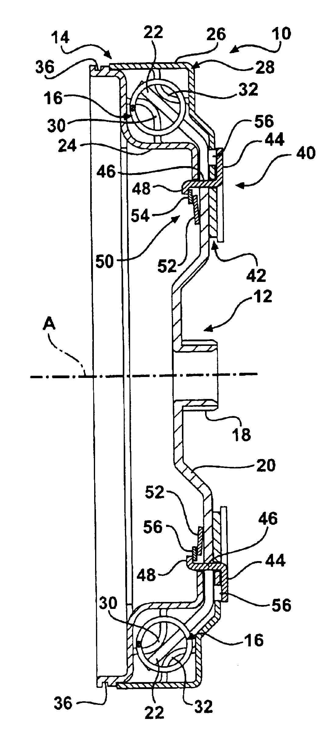
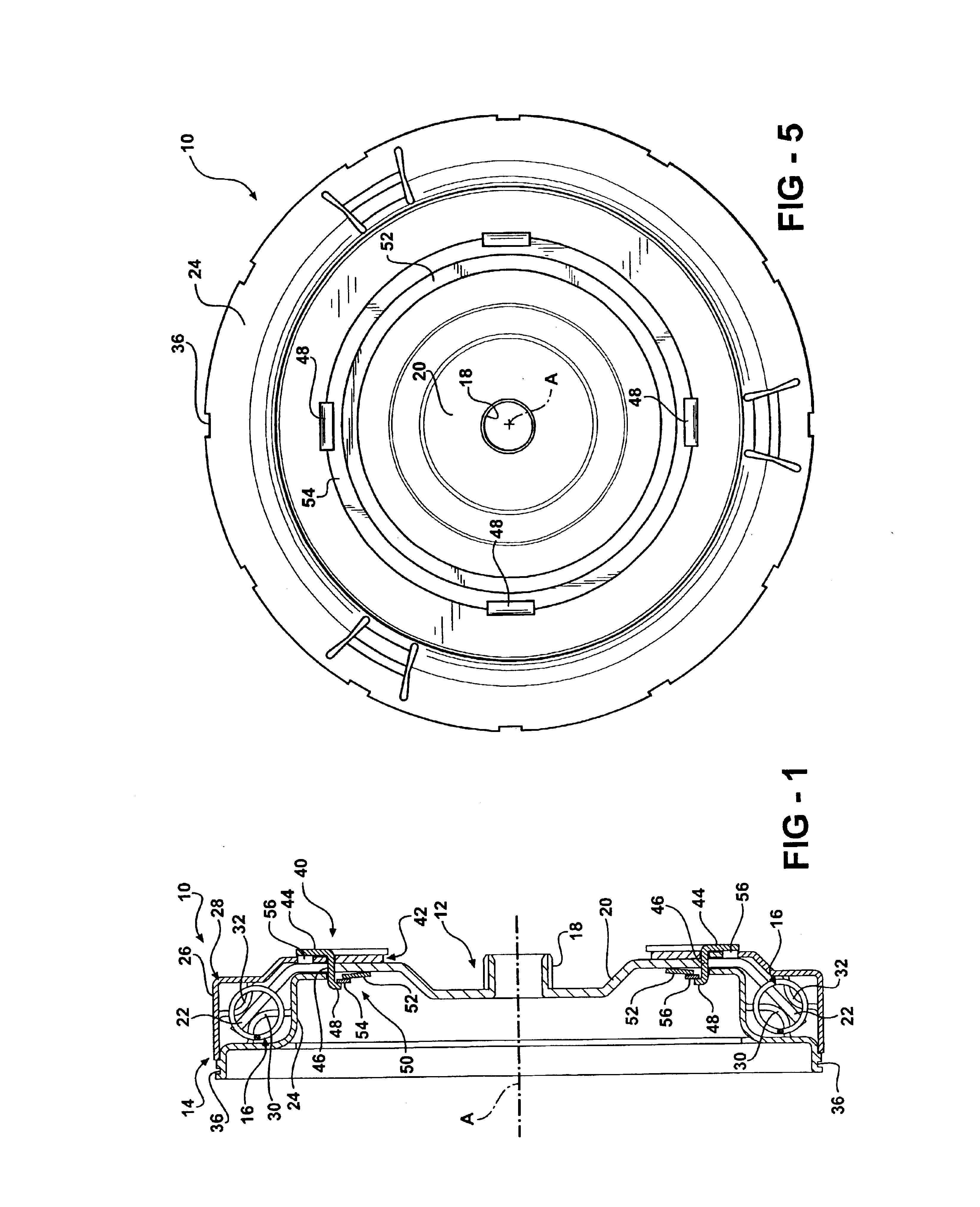
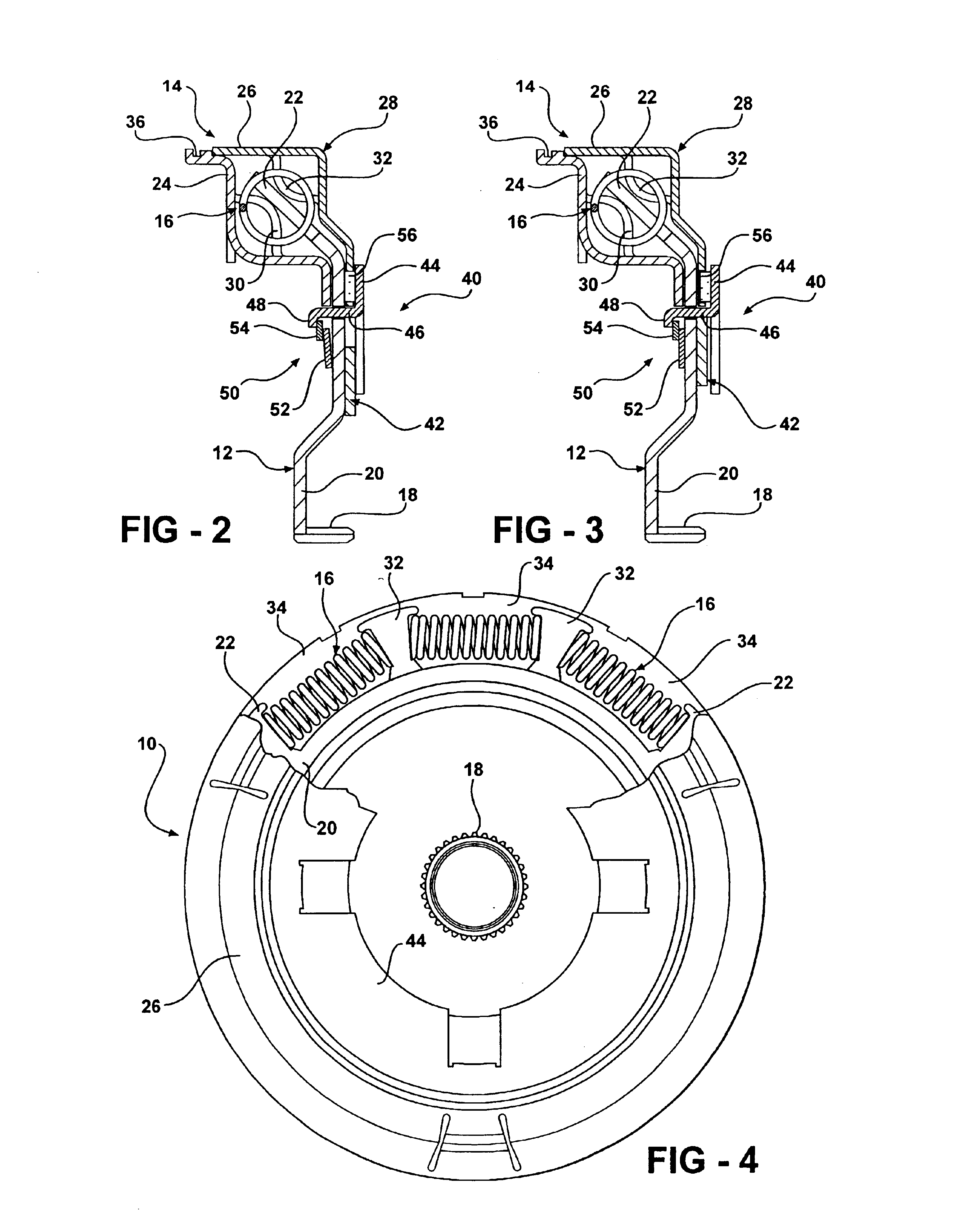
Referring now to the figures, where like numerals are used to describe like structure, a torsional damper that is adapted to be rotatably supported for translating torque between a prime mover such as an internal combustion engine (not shown) to the input shaft of a transmission is generally indicated at 10. The transmission may then subsequently distribute this power to one or more wheels (not shown) through other drivetrain components such as a drive shaft and an axle having a differential (also not shown). While the torsional damper illustrated in these figures is particularly adapted for use with an automotive vehicle, those having skill in the art will understand that the torsional damper of the present invention may be employed in connection with other types of transmissions.

The torsional damper 10 includes a torque input member, generally indicated at 12, that is operatively connected for rotation with the power take-off of the prime mover, an output member, generally indica...


PUM


Abstract

A torsional damper (10) rotatably supported for translating torque between a prime mover and the input of a transmission including a torque input member (12) that is operatively connected for rotation with the power take-off of a prime mover, an output member (14) operatively connected for rotation with the input to a transmission and a plurality of damping elements (16) interposed between the input member and the output member. The damping members (16) act to translate torque between the input and output members and to dampen torsional forces generated between the prime mover and the transmission. A bypass clutch (40) acts to translate torque directly between the input and output members thereby providing a path for partial torque translation that bypasses the damping elements at low rotational speeds of the input and output members. In addition, the torsional damper (10) includes a clutch release mechanism (42) that is responsive to centrifugal forces acting on the torsional damper to disengage the bypass clutch (40) to reduce the torque translated directly between the input and output members at high rotational speeds.

Description

BACKGROUND OF THE INVENTION1. Field of the InventionThe present invention relates, generally, to torsional dampers and, more specifically, to a torsional damper having a variable bypass clutch with a centrifugal release mechanism.2. Description of the Related ArtIn automotive applications, engine torque and speed are translated between a prime mover, such as an internal combustion engine, to one or more wheels through the transmission in accordance with the tractive power demand of the vehicle. Torque converters or start-up clutches are often employed between the internal combustion engine and its associated transmission.Torsional damping mechanisms are well known in the related art for reducing vibrations and torque pulses between the prime mover and the transmission. One torsional damping mechanism commonly known in the art includes a drive ring that forms an annular rearward facing channel and that may be mounted to a lock-up piston in the torque converter. A plurality of coiled ...

Claims


Application Information

Patent Timeline
Patent Type & Authority Patents(United States)
IPC IPC(8): F16H45/00F16F15/131F16D43/00F16D43/08F16H45/02
CPCF16D43/08F16H45/02F16F15/13128
Inventor BRAFORD, JR., THOMAS E.
Owner BORGWARNER INC
Why Eureka
Try Eureka