
Injection mold and method for manufacturing injection molded articles

a technology of injection molding and injection molds, which is applied in the direction of manufacturing tools, foundry molds, foundry patterns, etc., can solve the problems of reducing the strength at the material flow joint, reducing the area of the joint plane, and reducing the strength at the weld mark. , to achieve the effect of improving the joint plane area and favorable results

Inactive Publication Date: 2005-02-15
SHIN ETSU CHEM IND CO LTD
View PDF9 Cites 9 Cited by
  • Summary
  • Abstract
  • Description
  • Claims
  • Application Information

AI Technical Summary

Benefits of technology

An object of the invention is to provide an injection mold which enables to mold an article having a good outer appearance and improved strength at the material flow joint; and a method for manufacturing molded articles using the mold.
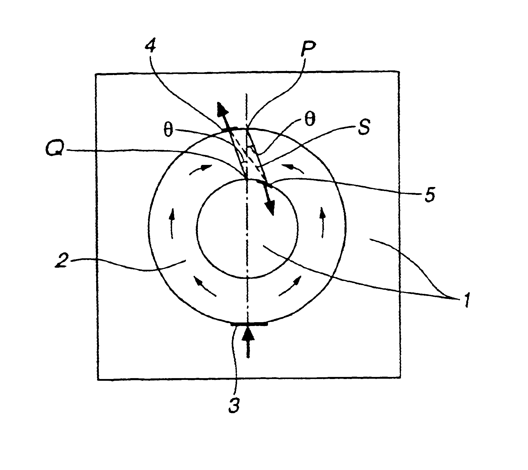
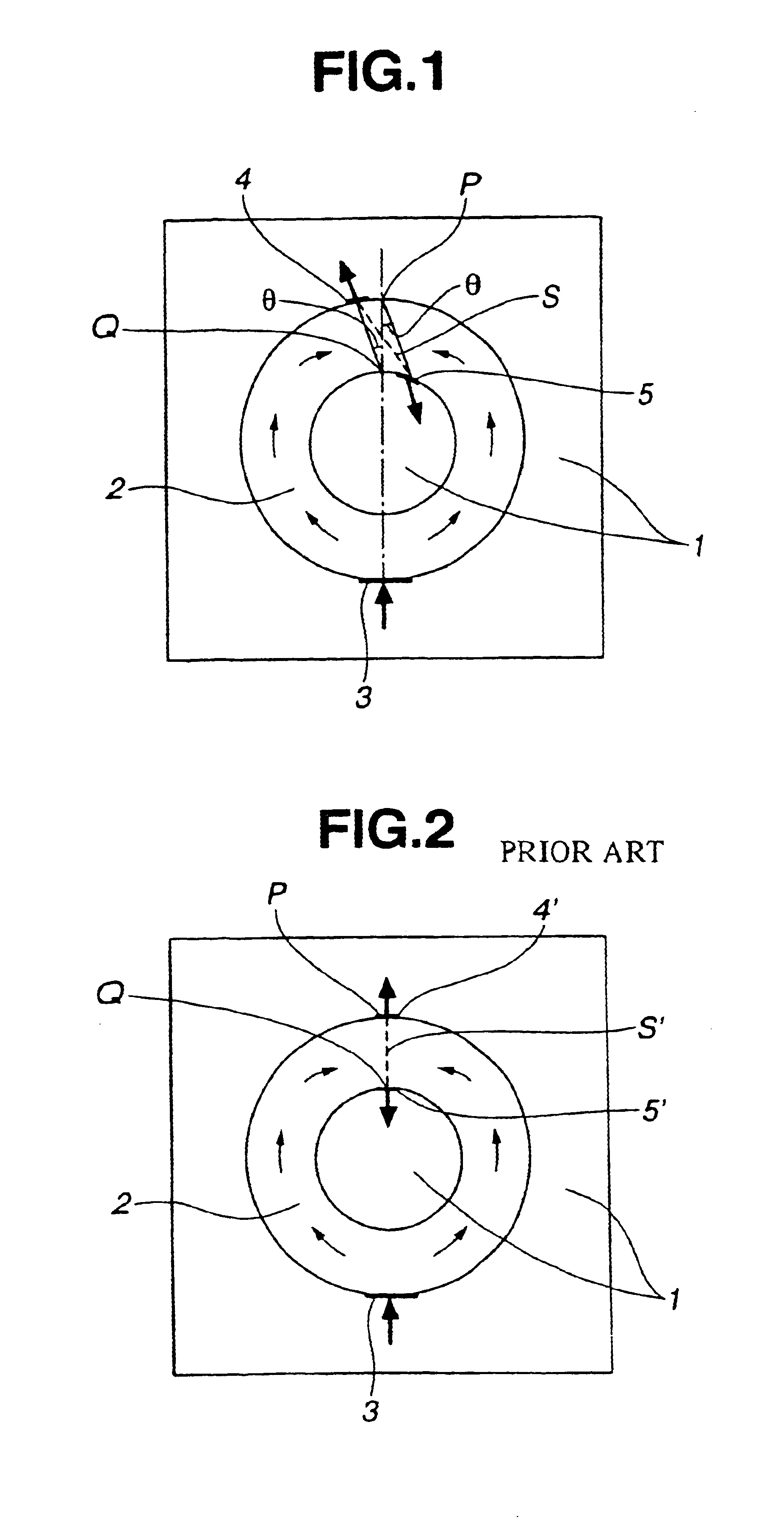
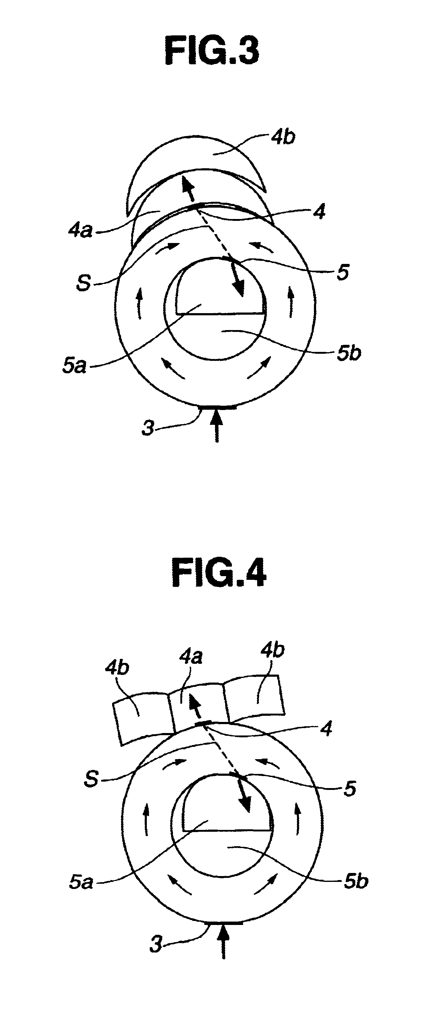
Specifically, in an injection mold having an article shape-defining cavity which entails a material flow joint and requires at least two air vent gates, the air vent gates are located at asymmetric positions with respect to the material flow joint plane, as embodied by the invention. Then the area of the material flow joint plane in the article molded using this mold is increased, whereby the material flow joint plane in the molded article is stabilized in strength and outer appearance. This is based on the belief that increasing the area of the joint plane by modifying the material streams to the joint plane is effective for stabilizing the joint of the material streams. Favorable results are obtained when a mold is designed based on this concept.

Problems solved by technology

The molds for injection molding have the problem that since their structures are often complex and a material flows in one direction, weld marks are frequently formed at the position where the material reaches latest.
Any strength lowering at weld marks is not permissible.
However, the fluororubber, when injection molded in a mold with a conventional air vent structure, tends to incur a strength lowering at the material flow joint and becomes insufficiently consistent in quality, although high reliability is necessary.
Undesirably, the compression molding method is incompliant with mass-scale production and low efficient.
However, they are difficult to produce articles in a consistent manner partly because they are difficult to mold by compression molding, and partly because an optimum mold structure has not been established for the liquid injection molding system (LIMS).

Method used


Image

  • Injection mold and method for manufacturing injection molded articles
  • Injection mold and method for manufacturing injection molded articles
  • Injection mold and method for manufacturing injection molded articles

Examples


example

Examples of the invention are given below by way of illustration and not by way of limitation.

The molding machine, mold and material used in Examples and Comparative Examples are described below.

Molding Machine

7-ton LIMS molding machine (trade name HM-7, LIMS specification, Nissei Resin Co., Ltd.)

10-ton LIMS molding machine (trade name NS-10, LIMS specification, Nissei Resin Co., Ltd.)

Mold

All molds made by PRC Co. whose product shape and dimensions, air vent shape and dimensions are shown in Table 1 and FIGS. 5 to 12.

Material

SIFEL 4750 (trade name of liquid fluororubber composition by Shin-Etsu Chemical Co., Ltd.)

SIFEL 3701 (trade name of liquid fluororubber composition by Shin-Etsu Chemical Co., Ltd.)

KE 1990-60 (trade name of liquid silicone rubber composition by Shin-Etsu Chemical Co., Ltd.)

TABLE 1O ring shapeInnerAir ventCavitydia-Thick-GatenumberMoldmeternessGatesizeDivi-in aNo.(mm)(mm)position(mm)sionmoldFigure124.993.53inventive6.0yes*4FIG. 5213.942.62inventive2.0no4FIG. 633.6...


PUM

PropertyMeasurementUnit
angleaaaaaaaaaa
volume ratioaaaaaaaaaa
thicknessaaaaaaaaaa

Abstract

In an injection mold comprising a cavity and a gate for feeding a molding material into the cavity, the molding material fed from the gate into the cavity is divided into two streams that flow through the cavity and then meet at a confluent point so that the molding material portions are joined together along a joint plane. Two air vent gates are spaced apart from the confluent point so as to provide a larger area of the joint plane. Articles having a good outer appearance and improved strength at the material joint can be consistently manufactured to a high precision.

Description

This invention relates to an injection mold suited for injection molding liquid rubber compositions into ring-shaped articles such as O rings and square rings, and a method for manufacturing injection molded articles using the mold.BACKGROUND OF THE INVENTIONInjection molding is suited to mass-scale production and advantageous for reducing the molding cycle and automatic operation. Molds for use in injection molding of, for example, ring-shaped articles such as rings and frames are generally configured such that a material enters a cavity (defining the article shape) from one gate and is divided into two streams which flow through the cavity and meet again at the position spaced remotest from the gate (where the material reaches latest).The molds for injection molding have the problem that since their structures are often complex and a material flows in one direction, weld marks are frequently formed at the position where the material reaches latest. In the injection molding of seal...

Claims


Application Information

Patent Timeline
Patent Type & Authority Patents(United States)
IPC IPC(8): B29C45/00B29C45/34B29C45/26F16J15/10B29K19/00B29K21/00B29L31/26F16J15/20
CPCB29C45/0025B29C45/2616B29C45/34Y10S425/042B29C2045/0044B29C45/2628
Inventor OSAWA, YASUHISASATO, MAKOTO
Owner SHIN ETSU CHEM IND CO LTD
Learn More