Synchronous resolver, resolver cable and direct drive motor system

a resolver and motor technology, applied in the direction of motor/generator/converter stopper, dynamo-electric converter control, shape/form/construction of magnetic circuits, etc., can solve the problems of reducing the precision of position detectors, and affecting the operation of motors. the effect of reducing electrical interference and excellent repair and maintenan

Inactive Publication Date: 2005-02-15
NSK LTD
View PDF5 Cites 11 Cited by
  • Summary
  • Abstract
  • Description
  • Claims
  • Application Information

AI Technical Summary

Benefits of technology

Use of the present structure can correct variations in the positions of the coils of the resolvers, thereby being able to provide a compatible direct drive motor system. Also, in the case of replacement of the direct drive motor, since the compatibility of the direct drive motor system is secured, the present system is excellent in repair and maintenance.
Also, the resolver cable may be structured such that the distances between the signal lines of the respective phases of the polyphase resolver signals as well as the distances between the respective signal lines and common lines are set substantially uniform. Use of this structure can reduce electrical interference between the signal lines.

Problems solved by technology

In case where the windings of the respective phases vary in the winding number, inductance, and resistance values, there is generated an imbalance in the signals of the three phases to cause an error in a true value, thereby degrading the precision of a position detector.
On the other hand, in the conventional resolver apparatus, in a three-phase AC exciting winding is directly wound around a substantially T-shaped magnetic pole projectingly provided on a stator, it is also very difficult to realize a uniform winding state for a large number of magnetic poles, which causes the resolver signals between the respective phases to vary.
Since such variations according to individual motors are caused by variations in the sizes of the d.c. components (A1, B1, C1) of the respective phases, the above-mentioned correction by the driver is not able to cope with such variations.
However, in case where the position relationship of the respective detect signals within the resolver cables is asymmetric, due to variations in the lengths of the cables, there is caused electrical interference.
And, in the case of the resolver cables used in the direct drive motor system, there also arises a problem as to their compatibility.
This imbalance, when the length of the cable is changed, has an influence on the respective phase detect signal lines and thus gives rise to an error in the absolute precision of the resolver signal cable.
As described above, in case where the values of the electrostatic capacity between the exciting signal line and the respective phase detect signal lines of the resolver signal cable do not balance well, when the length of a cable is changed freely, or when a very long cable is used, there occurs electrical interference between the signal lines due to the imbalance between the values of the electrostatic capacity thereof, which gives rise to errors in the measurement of the resolver.
That is, the conventional manner of cable selection, in which a cable is selected simply because it is small in line electrostatic capacity, is not always be able to secure the satisfactory fulfillment of the function of the resolver.
Especially, since a signal flowing in a resolver signal cable is a minute analog current, there is influenced by the length of the cable, which is prone to degrade the precision of the resolver.

Method used


Image

  • Synchronous resolver, resolver cable and direct drive motor system
  • Synchronous resolver, resolver cable and direct drive motor system
  • Synchronous resolver, resolver cable and direct drive motor system

Examples


Embodiment Construction

Now, description will be given below of an embodiment of a direct drive motor system according to the invention with reference to the accompanying drawings.

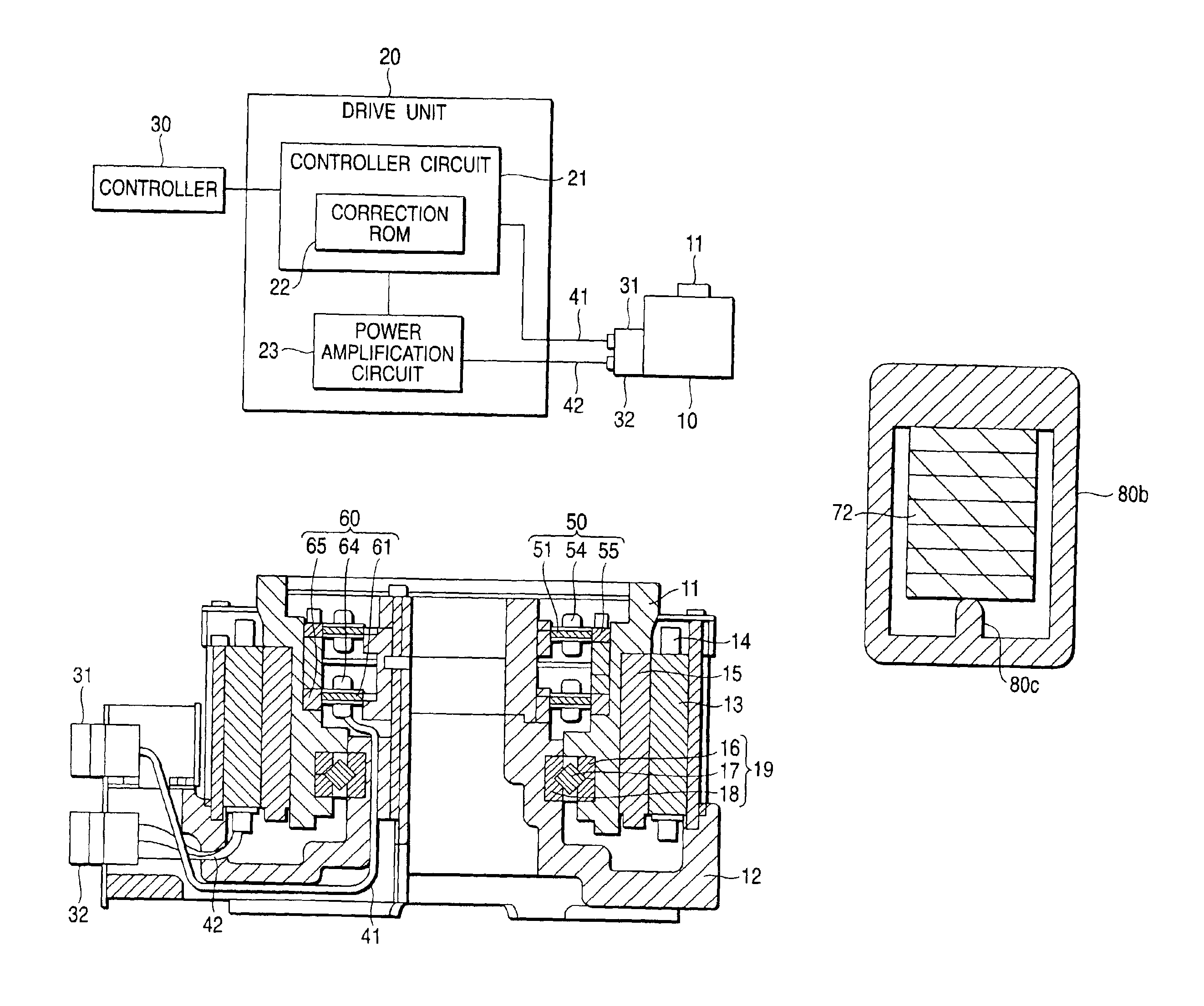
FIG. 1 is a block diagram of the structure of a direct drive motor system according to the present embodiment. This system comprises a direct drive motor 10 for rotationally driving a rotary shaft 11, a drive unit 20 for driving and controlling the direct drive motor 10, and a resolver cable 41 and a motor cable 42 which are respectively used to connect together the motor 10 and unit 20. The driver unit 20 includes a controller circuit 21 and a power amplification circuit 23. Specifically, the controller circuit 21 not only supplies an exciting signal through the resolver cable 41 and a resolver terminal 31 to an absolute position detecting resolver and a relative position detecting resolver respectively built in the direct drive motor 10, but also takes in polyphase resolver signals output from the respective resolvers to conver...


PUM


Abstract

A synchronous resolver has: a stator including a plurality of stator poles disposed at regular intervals along the circumferential direction of a ring-shaped stator base portion, the stator poles comprise a plurality of phases; coil bobbins former-wounded stator coils therearound are respectively fitted with and mounted on their associated ones of the stator poles; and, a rotor shiftable in angle with respect to the stator to thereby vary a reluctance component in a gap existing between the stator and the rotor, wherein the coil bobbins are set the positions of the stator coils freely in such a manner that the resolver signals of the respective phases balance well.

Description

BACKGROUND OF THE INVENTION1. Field of the InventionThe present invention relates to an improvement in a direct drive motor system including a synchronous resolver of a variable reluctance type and a cable to connect the resolver and a driver unit.Hereinafter, in a case of that “synchronous resolver” is called simply “resolver”, the “resolver” is used as same meaning as the “synchronous resolver”.In particular, the present invention relates to an improvement in a technique for correcting variations in windings of a synchronous resolver to thereby secure compatibility between products.In particular, the present invention relates to a wiring structure for a cable for transmitting a resolver signal which is used to detect the rotation angle position of a motor.2. Description of the Related ArtAs a detector for detecting the rotation angle position of a direct drive motor which drives a load directly without using a decelerator, in Japanese Patent No. 3060525, there is disclosed a resol...

Claims


Application Information

Patent Timeline
Patent Type & Authority Patents(United States)
IPC IPC(8): G01D3/02H02K24/00
CPCH02K24/00G01D3/022
Inventor NISHIZAWA, MASATOSHIKUWAHARA, MASAKIKAMIMURA, MASAMITSU
Owner NSK LTD
Why Eureka
Try Eureka