
Control circuitry for high speed video camera operation

a control circuit and video camera technology, applied in closed-circuit television systems, color television details, television systems, etc., can solve the problems of device applicable, no satisfactory means of obtaining video images, etc., and achieve the effect of convenient use, accurate and inexpensive control methods, and simple manufacturing

Inactive Publication Date: 2005-02-15
THE GOVERNMENT OF THE UNITED STATES OF AMERICA AS REPRESENTED BY THE SEC OF THE NAVY NAVAL RES LAB WASHINGTON
View PDF6 Cites 2 Cited by
  • Summary
  • Abstract
  • Description
  • Claims
  • Application Information

AI Technical Summary

Benefits of technology

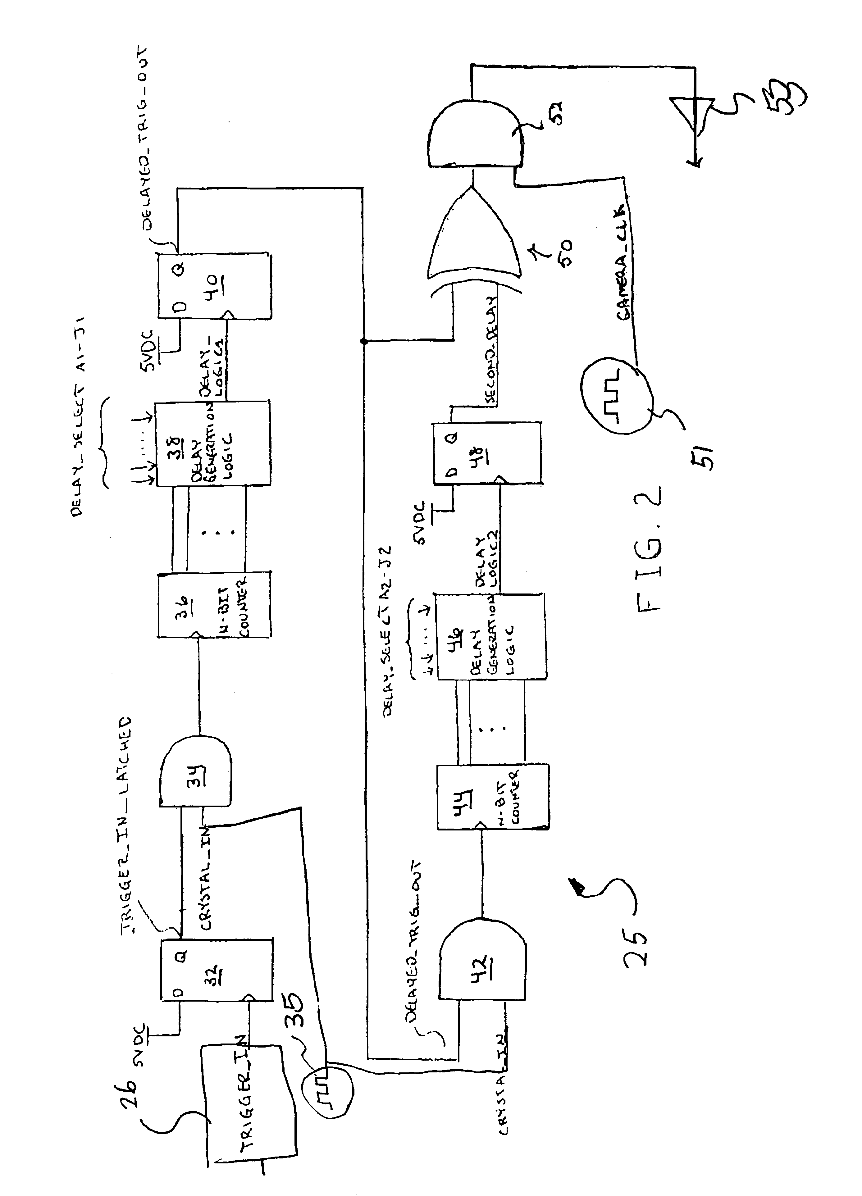
"This patent describes a device and circuitry for controlling a video camera in underwater high speed photography. The device includes a plurality of sensors, a projectile, a camera, and an illumination source. The control circuitry includes a first D flip flop, an AND gate, an N-bit counter, a second D flip flop, a second AND gate, a second delay generation logic block, a third D flip flop, an exclusive OR gate, and a camera clock generator. The device can accurately and inexpensively control the timing of operation of the video camera in underwater high speed photography. The circuitry is simple to manufacture and easy to use."

Problems solved by technology

Prior to this time, there was no satisfactory means of obtaining the video images that were needed, nor was there a device applicable to a variety of conditions.

Method used


Image

  • Control circuitry for high speed video camera operation
  • Control circuitry for high speed video camera operation
  • Control circuitry for high speed video camera operation

Examples


Embodiment Construction

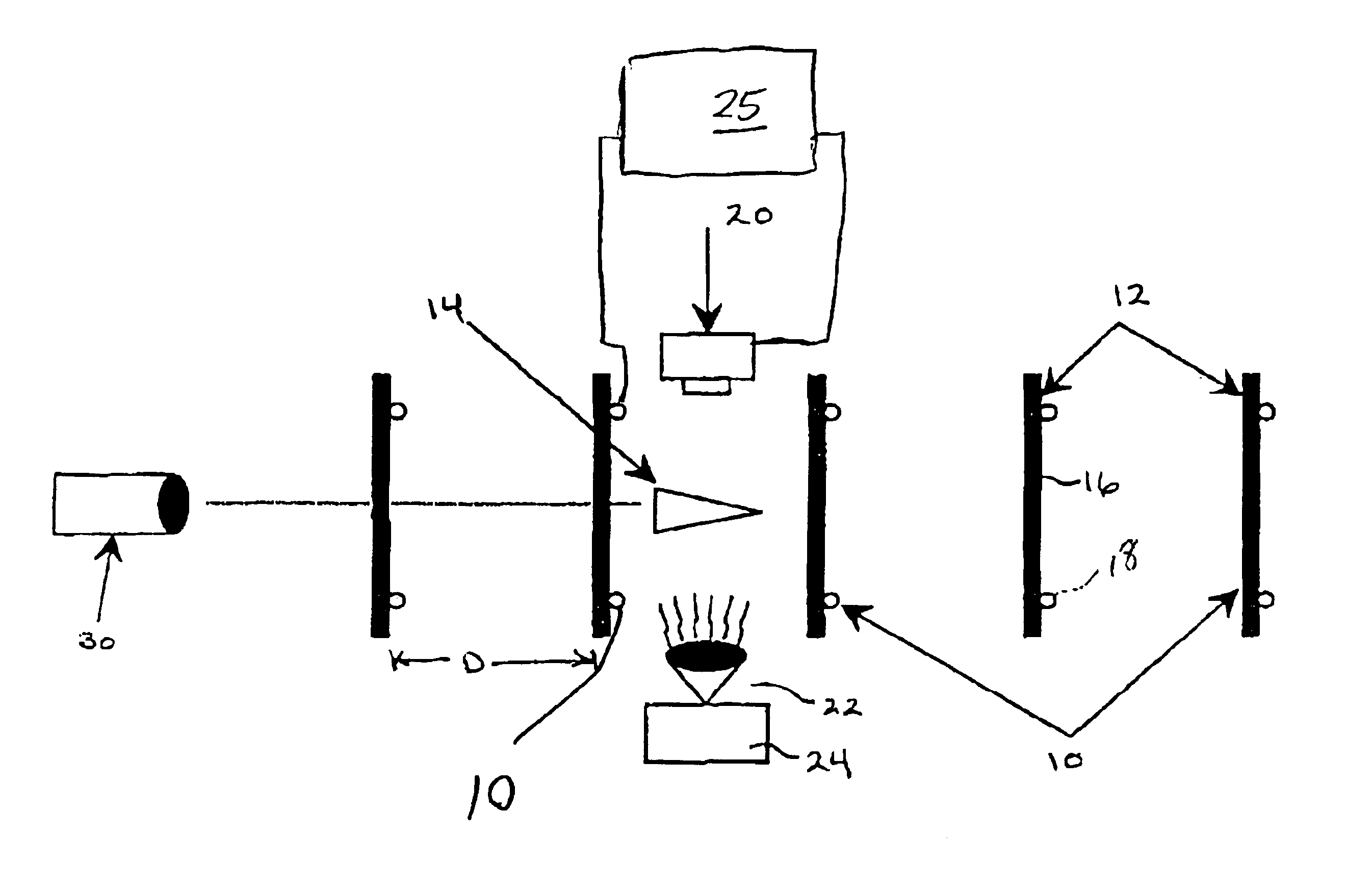
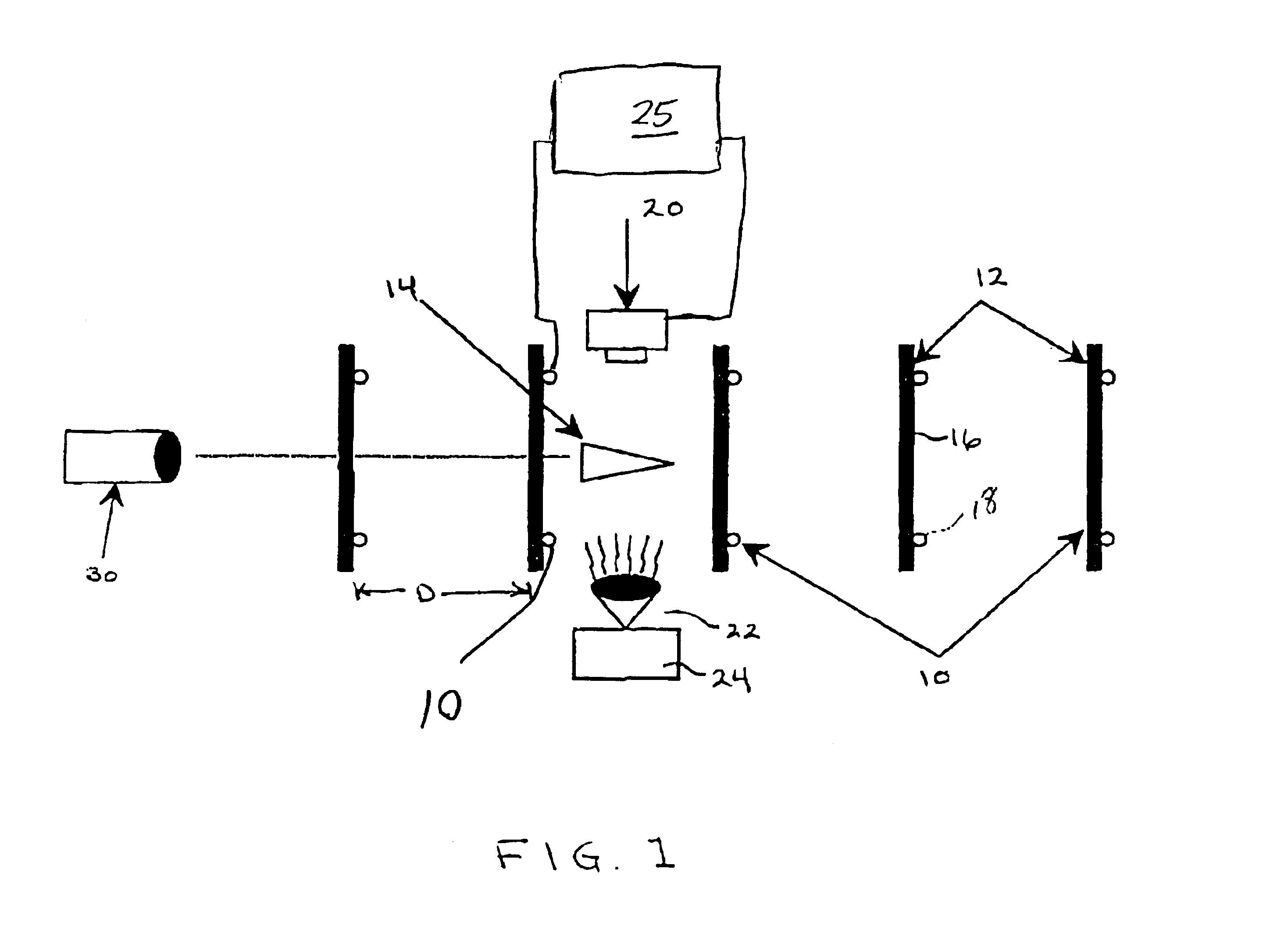
In general, the present invention is directed to a control circuitry for controlling an underwater video camera for the purpose of taking underwater video images of a high speed projectile tested in the Adaptable High Speed Underwater Munition (AHSUM) project. The control circuitry essentially senses when the projectile has passed through a break screen or sensing coil and provides a trigger signal in response thereto. The control circuitry uses this trigger to enable its novel timing scheme to turn on the video camera at the exact time required to acquire the video images.

Referring first to FIG. 1, there is shown a simple diagram of the test set up including a plurality of sensing devices 10 all spaced a predetermined distance D apart. These sensing devices 10 can be either sensing coils or break screens. Each sensing device 10 is mounted to a steel plate 12 having an opening formed therein for passage of a projectile 14 therethrough as discharged from a gun 30. The opening may be ...


PUM


Abstract

A device for controlling a video camera in underwater high speed photography in a first aspect includes a plurality of spaced break screen or sense coil members, a projectile for launch through the series of break screen or sense coil members, a video camera operated to video at a predetermined timing upon release of the projectile, and a source of illumination to aid in the video photography. A trigger device such as a break screen or sense coil is positioned immediately up-range of the video camera. With a time delay programmed into a Programmable Array Logic (PAL), a control circuitry receives the trigger information and creates a timed signal to control the operation of the video camera. In accordance with another aspect of this invention, the control circuitry includes discrete logic devices programmed such that gating of the video camera is controlled by the control circuitry at the time the projectile passes the lens of the camera.

Description

BACKGROUND OF THE INVENTION(1) Field of the InventionThis invention relates high speed photography, and to a circuit for triggering a video camera located between two sensors. More specifically, the video camera is triggered by a projectile passing through a break screen on an underwater range.(2) Description of the Prior ArtThe Adaptable High Speed Underwater Munition (AHSUM) project needed a method to obtain video images of underwater projectiles during the course of their test series. Prior to this time, there was no satisfactory means of obtaining the video images that were needed, nor was there a device applicable to a variety of conditions.The following patents, for example, disclose various types of video photography, including underwater photography and circuits in connection therewith, but do not disclose a device for controlling an underwater video camera for the purpose of taking underwater video of a high speed projectile.U.S. Pat. No. 4,335,944 to Marshall;U.S. Pat. No....

Claims


Application Information

Patent Timeline
Patent Type & Authority Patents(United States)
IPC IPC(8): H04N7/18H04N5/232H04N5/235
CPCH04N5/23203H04N7/183H04N5/2353H04N23/66H04N23/73
Inventor RAPOSA, JOHN R.THIVIERGE, DANIEL P.
Owner THE GOVERNMENT OF THE UNITED STATES OF AMERICA AS REPRESENTED BY THE SEC OF THE NAVY NAVAL RES LAB WASHINGTON
Learn More