Diffractive optical element for providing favorable multi-mode fiber launch and reflection management

a multi-mode fiber and diffractive technology, applied in the field of optical elements, can solve the problems of laser source instability, laser destabilization, and may operate with a noisy output signal, and achieve the effect of avoiding index anomalies and favorable launch conditions

Inactive Publication Date: 2005-02-15
BROADCOM INT PTE LTD
View PDF4 Cites 29 Cited by
  • Summary
  • Abstract
  • Description
  • Claims
  • Application Information

AI Technical Summary

Benefits of technology

According to one embodiment of the present invention, a transfer lens for transferring light emitted by a light source (e.g., a laser) into a light conducting medium (e.g., an optical fiber) is provided. The transfer lens includes a diffractive surface for receiving and collimating the light originating from the light source. The diffractive surface is defined by a surface function that includes a first phase function having angular symmetry and a second phase function having radial symmetry. The second phase function includes a cusp region with a discontinuous slope therein. The transfer lens provides reflection management so that light reflected from the end of the optical fiber is not focused at a location at which light is emitted by the light source. Furthermore, the transfer lens also provides favorable launch conditions so that light launched into the optical fiber avoids index anomalies on the axis of the optical fiber and at the core-cladding interface.
A further advantage of the transfer lens design of the present invention is that the diffractive surface of the transfer lens provides reflection management and favorable launch conditions, which is particularly advantageous for multi-mode fiber optic systems.
In accordance with one embodiment of the present invention, a light transmission system that includes a laser, an optical fiber, and a transfer lens is provided. The transfer lens transfers light emitted by the laser into the optical fiber. The transfer lens includes a diffractive surface for receiving and collimating the light originating form the laser. The diffractive surface is defined by surface function that includes a first phase function having angular symmetry and a second phase function having radial symmetry. The second phase function includes a cusp region with a discontinuous slope therein. The transfer lens provides reflection management so that light reflected from the end of the optical fiber is not focused at a location at which light is emitted by the laser and also favorable launch conditions so that light launched into the optical fiber avoids index anomalies along the axis of the optical fiber.

Problems solved by technology

When reflections are not managed properly, the back reflections can cause stability problems for the laser source.
Specifically, if these back reflections are not controlled or reduced, the laser can become de-stabilized and may operate with a noisy output signal.
For example, when too much power is coupled back into the laser from the reflection from the end of the optical fiber, instabilities occur in the laser, and the output power oscillates up and down, thereby causing extra and damaging amounts of jitter as the received signal pulses.
In other words, instability in the laser causes erroneous data signals.
Furthermore, the increased noise in the laser that is induced by the coupling lens can lead to a power penalty in the optical budget of the data link as high as 2.5 dB.
This adverse effect of back reflections or feedback becomes more pronounced and significant for higher data rate systems.
A reason for avoiding the center of the fiber is that many fibers have defects along the center of the fiber due to manufacturing limitations.
Otherwise, misalignment in the system (e.g., misalignment between the optical fiber and transfer lens or the misalignment between the transfer lens and the laser) may cause the light from the laser to miss the optical fiber.
Unfortunately, the prior art transfer lens designs have shortcomings in either addressing back reflections or providing favorable launch conditions.
These shortcomings and disadvantages stem primarily from constraints and difficulties in lens fabrication.
While these prior art approaches provide tolerable results for ideal point light sources (i.e., light that has a simple distribution and is perfectly coherent), these approaches do not adequately address applications that employ light sources with more complex light distributions (e.g., a multi-mode laser).
In these specific real-world applications, the prior transfer lens suffer from more destabilizing feedback due to poor management of back reflections, unfavorable launch conditions stemming from larger amounts of on-axis energy, or both.

Method used


Image

  • Diffractive optical element for providing favorable multi-mode fiber launch and reflection management
  • Diffractive optical element for providing favorable multi-mode fiber launch and reflection management
  • Diffractive optical element for providing favorable multi-mode fiber launch and reflection management

Examples


embodiment

Preferred Embodiment

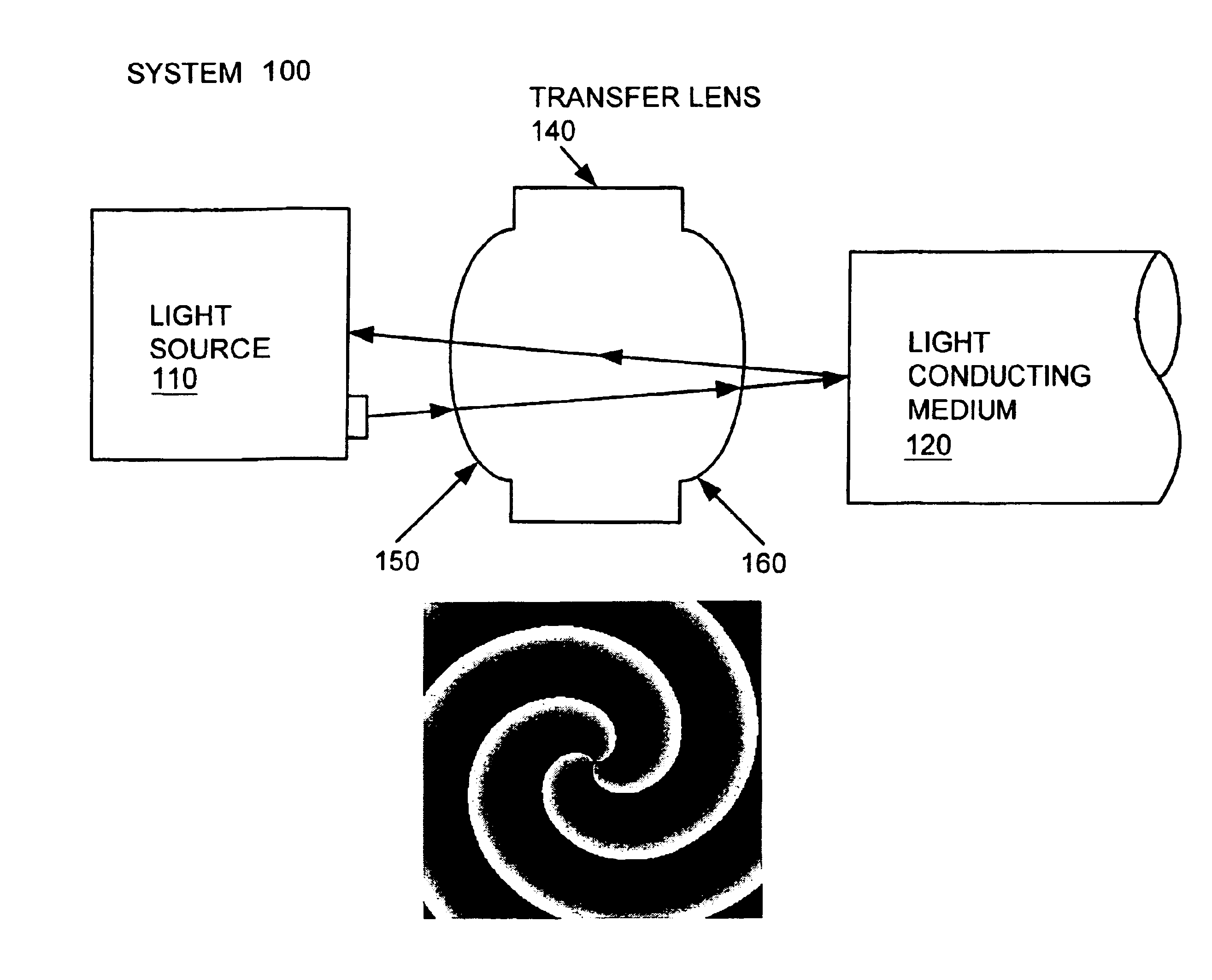
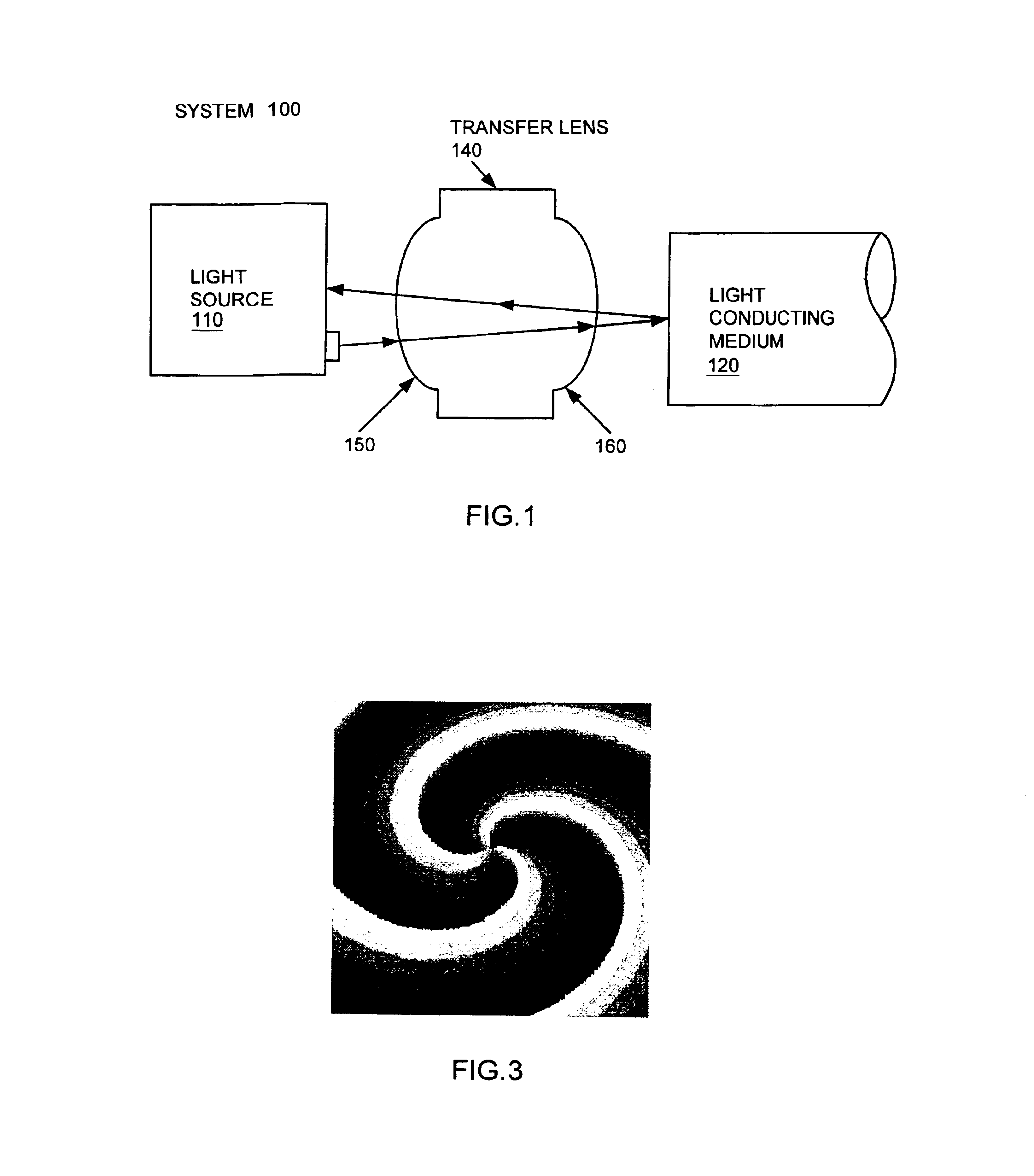
Preferably, the design of the diffractive element of the present invention includes at least two phase functions (i.e., the first phase function having angular symmetry combined with the second phase function having radial symmetry) described above.

Describe the phase, φ, of all points within the lens aperture with polar coordinates: ρ,θ, where ρ is the distance of the point from the center of the aperture, and θ is the angle of the point from the x-axis.

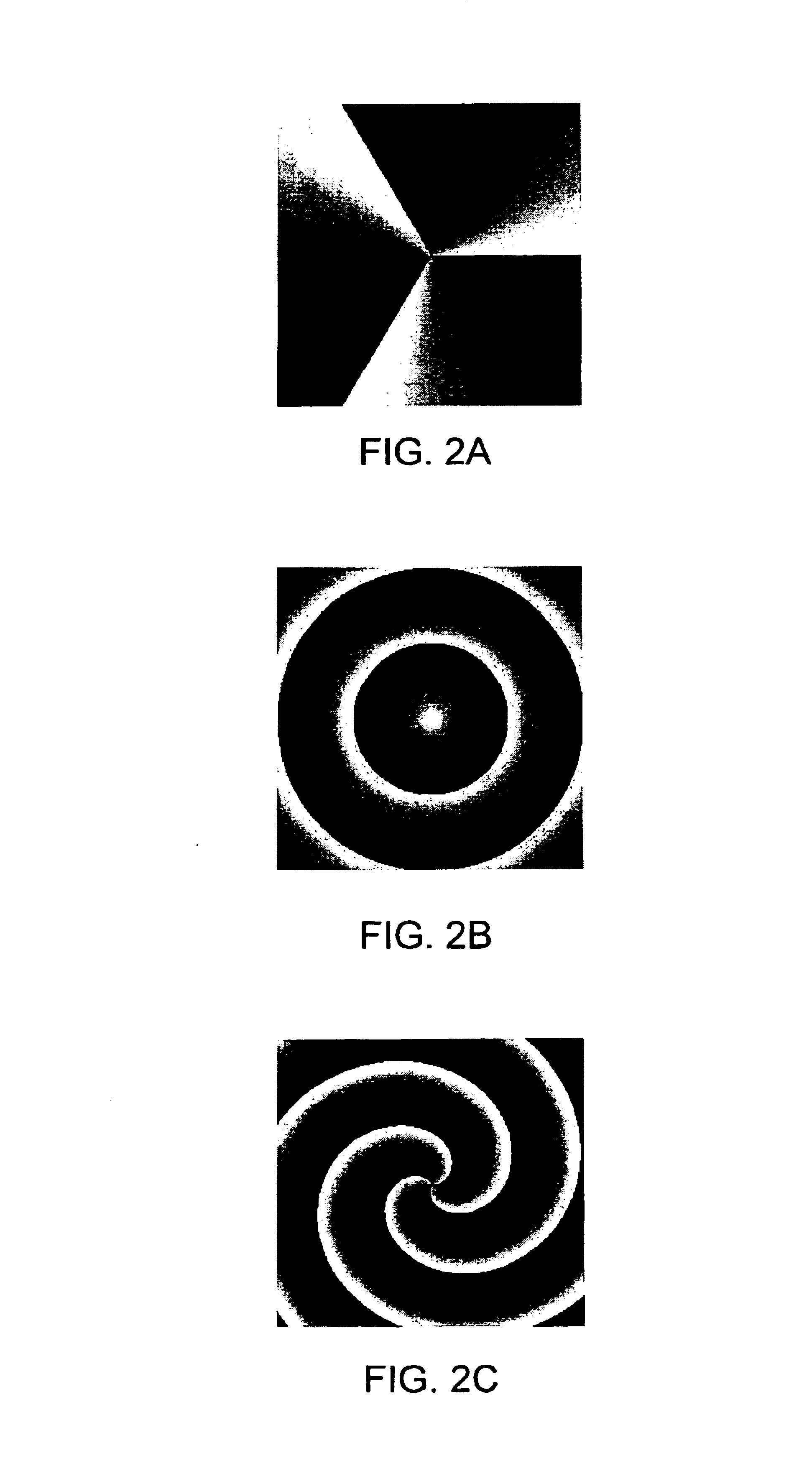
In the preferred embodiment, the surface function of the diffractive element of the present invention includes at least a first phase function having angular symmetry (e.g., a spiral phase function) combined with a second phase function having radial symmetry (e.g., a cone phase function). For example, the surface function can be expressed as follows:

φ=mS*θ+2πmC*ρ.

The spiral phase function can be expressed as follows:

φ=mS*θwhere ‘mS’ is a real number, −INF to +INF, that describes how fast the phase changes as one ...


PUM


Abstract

A light transmission system includes a laser, an optical fiber, and a transfer lens. The transfer lens transfers light emitted by the laser into the optical fiber. The transfer lens includes a diffractive surface for receiving and collimating the light originating form the laser. The diffractive surface is defined by a surface function that includes a first phase function having angular symmetry and a second phase function having radial symmetry. The second phase function includes a cusp region with a discontinuous slope therein. The transfer lens provides reflection management so that light reflected from the end of the optical fiber is not focused at a location at which light is emitted by the laser and also favorable launch conditions so that light launched into the optical fiber avoids index anomalies along the axis of the optical fiber.

Description

FIELD OF THE INVENTIONThe present invention relates generally to optics, and more particularly, to a diffractive optical element that provides favorable multi-mode fiber launch and reflection management.BACKGROUND OF THE INVENTIONA vertical cavity surface emitting laser (VCSEL) emits light in a beam vertically from it surface. Light emitted from a VCSEL is typically focused by a transfer lens into an optical fiber and used for the transmission of data. Transmission technology such as Gigabit Ethernet technology utilizes VCSELs and multimode fiber optic cabling.The ever-increasing data rate across multimode fiber optic systems requires more sophisticated coupling optics for the transmitter module to satisfy the required bit-error rate.There are two important considerations in the design of a transfer lens: 1) reflection management, and 2) creation of a favorable launch condition. The first design consideration of reflection management seeks to minimize the amount of light that is ref...

Claims


Application Information

Patent Timeline
Patent Type & Authority Patents(United States)
IPC IPC(8): G02B5/18G02B6/42G02B27/42G02B3/02
CPCG02B5/1814G02B6/4207G02B6/4206G02B27/42
Inventor COLEMAN, CHRISTOPHER L.CHEN, YE CHRISTINE
Owner BROADCOM INT PTE LTD
Why Eureka
Try Eureka