Contact member to optical disk, protecting film for optical disk and coating composition

a technology of contact member and optical disk, which is applied in the direction of instruments, flat record carrier containers, disposition/mounting of heads, etc., can solve the problems of lens colliding, cd and dvd recording surface of optical disk may be abraded and damaged at a disk, and the objective lens or the recording surface of optical disk may be damaged, etc., to prevent scratches on the recording surface, excellent slidability and elastic deformation, and excellent lubrication

Inactive Publication Date: 2005-02-15
AKROS +1
View PDF6 Cites 12 Cited by
  • Summary
  • Abstract
  • Description
  • Claims
  • Application Information

AI Technical Summary

Benefits of technology

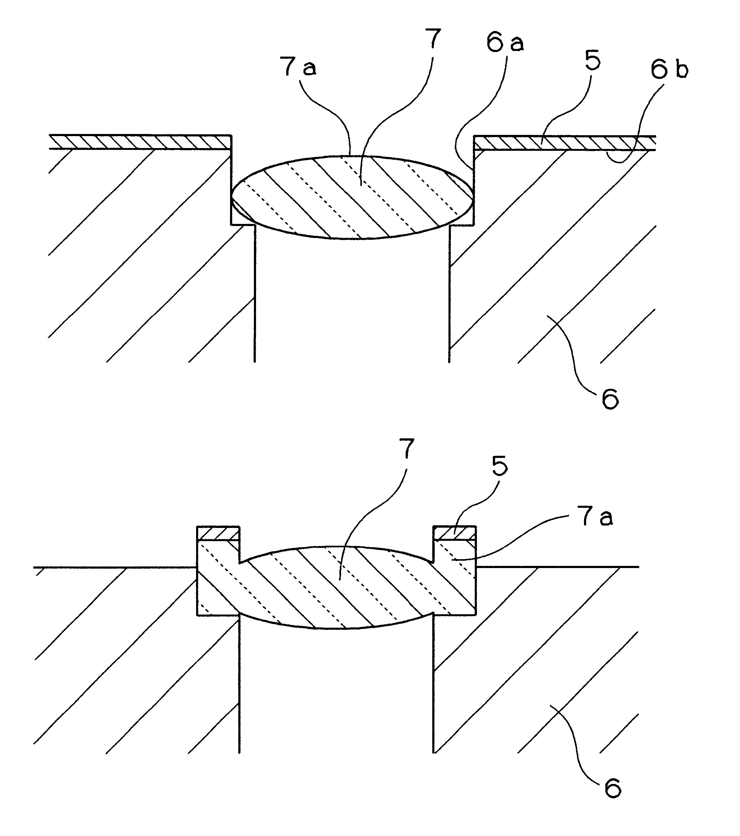
In order to prevent scratches on the recording surface of the optical disk, the portion that is contacted with the optical disk is coated with a coating film having excellent lubricity to relax the attack to the optical disk utilizing its slidability. For example, fluororesin may be compounded or diffused in the coating film. However, experiments prove that such a coating film cannot prevent the scratches on the optical disk rotated at high speed. According to the present invention, the coating film comprising the urethane resin as a base, and at least the polyurethane particles and the fluororesin powder is formed on the portion that is contacted with the optical disk. It is found that excellent slidability and elastic deformation of the coating film relax the collision or friction to the optical disk, resulting in the contact member to the optical disk that does not produce scratches. The present invention is based on such discovery.

Problems solved by technology

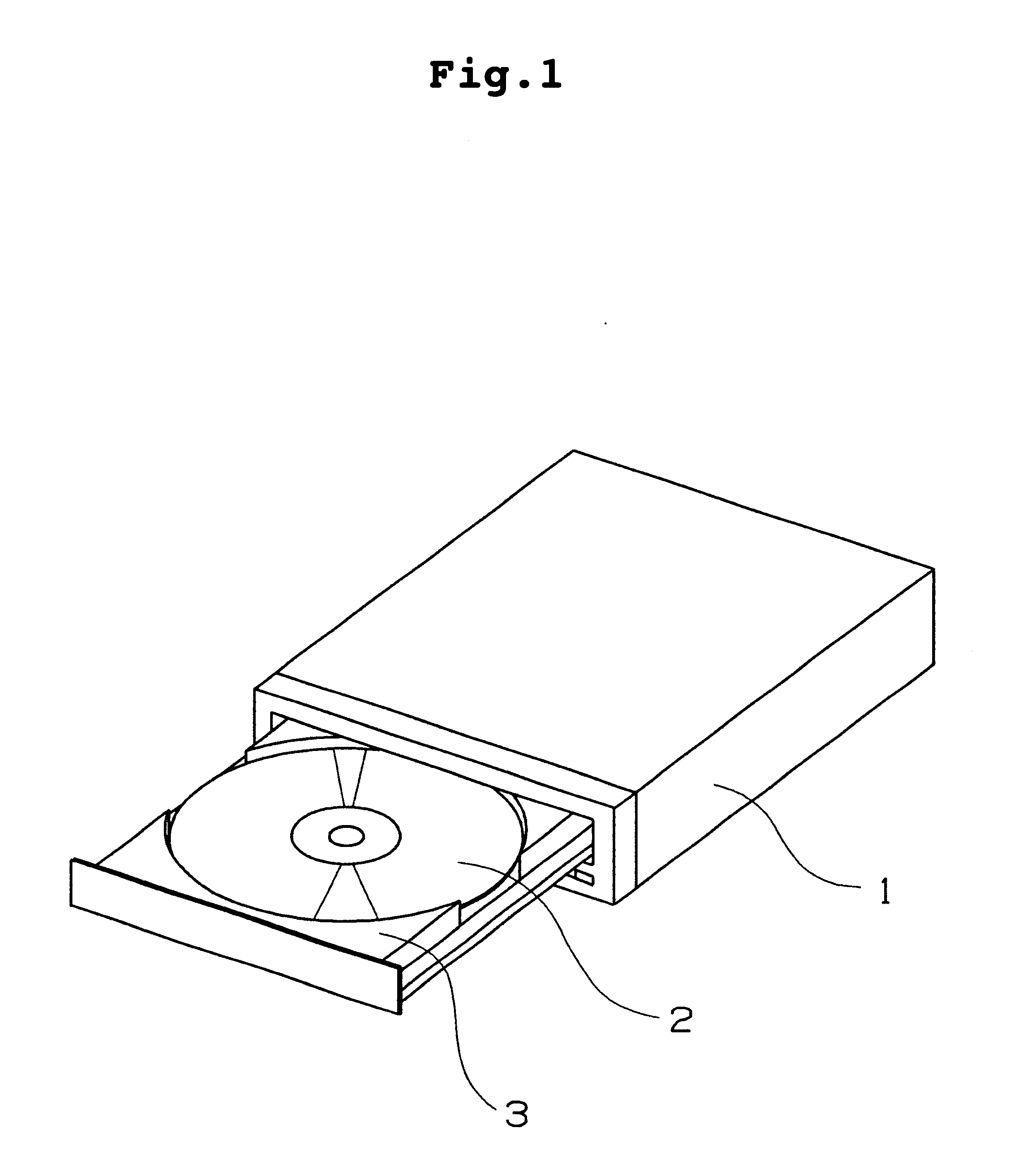
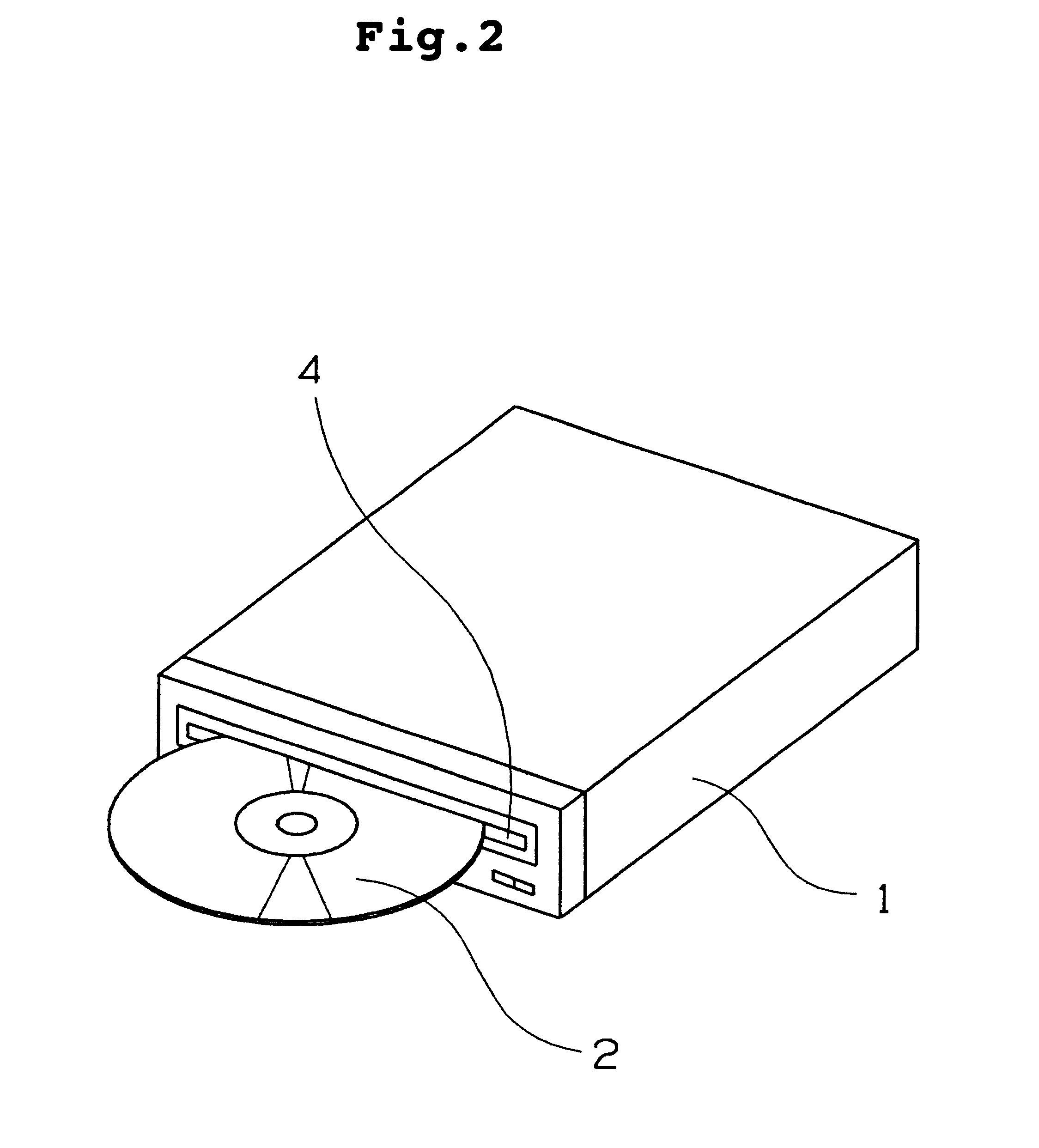
The former type that the optical disk itself is inserted into the optical disk apparatus has a problem that a recording surface of the optical disk such as the CD and the DVD may be abraded and damaged at a disk insertion.
When the optical disk is impacted accidentally during the CD or DVD reading or recording, an objective lens or the recording surface of the optical disk may be damaged.
The optical disk apparatus having a property to collect light using the same lens as to the CD and the DVD has a problem that the objective lens collides with the optical disk due to a difference in a working distance.
The objective lens or the recording surface of the optical disk may be damaged.
However, in the DVD and the optical disk using the helium neon laser, the damaged recording surface of the optical disk or the damaged objective lens may adversely affect reading properties of the optical disk than ever before.
For example, even though a tray and the disk insertion of the optical disk apparatus are made of a polyacetal resin that is softer material than that of the optical disk, it is difficult to completely prevent scratches that may adversely affect the reading properties of the recording surface of the optical disk.
The cushioning material such as the polyacetal resin, the rubber and the felt suffer from significant creep or elastic deformation.
It is therefore difficult to completely prevent the collision of the objective lens and the optical disk.

Method used


Image

  • Contact member to optical disk, protecting film for optical disk and coating composition
  • Contact member to optical disk, protecting film for optical disk and coating composition
  • Contact member to optical disk, protecting film for optical disk and coating composition

Examples


example 1

Polyester polyol and TDI were mixed at an equivalent ratio (hydroxyl group / isocyanate group) of 1.0 so that the resin had elongation at break after curing was 126%. 100 parts by weight of the mixture was dissolved in 100 parts by weight of methyl ethyl ketone and 100 parts by weight of butyl acetate. 40 parts by weight of polyurethane particles having a mean diameter of 15 to 25 μm manufactured by Dainippon Ink and Chemicals, Incorporated under the tradename of CFB100, and 20 parts by weight of fluororesin powder having a mean diameter of 4 μm manufactured by Sumitomo 3M Limited under the tradename of Dainion TF9207 were dispersed therein to provide a scratch resistant coating composition.

The coating composition was coated on a steel ball with a diameter of 5 mm so that a cured coating had a thickness of 40 to 50 μm, and cured at 80° C. for 60 minutes to produce a test piece for evaluation. The test piece was evaluated using a CD-R manufactured by Taiyo Yuden Co., Ltd. on a pin-on-d...

examples 2 to 13

Scratch resistant coating compositions were prepared as in EXAMPLE 1 except that materials and mixing ratios shown in TABLE 1 were used. In EXAMPLE 13, block isocyanate was used and curing was conducted at 140° C. for 30 minutes. In TABLE 1, the materials are based on parts by weight.

The scratch resistant coating compositions were evaluated under the same conditions in EXAMPLE 1. The results are shown in TABLE 1.

TABLE 1Example2345678910111213Coating composition, parts by weightPolyester polyol + TDI OH / NCO = 1.0 (126)*1100100——————————Polyester polyol + HDI OH / NCO = 1.0 (400)*1——100100————————Polyester polyol + TDI OH / NCO = 0.7 (210)*1————100———————Polyester polyol + HDI (urethane adduct type) OH / NCO = 1.5—————100——————(280)*Thermoplastic polyurethane resin (800)*1——————100100————(Acrylic polyol:PTMG = 8:2) + TDI OH / NCO = 1.0 (100)*1————————100———(FEVE:PTMG = 8:2) + TDI OH / NCO = 1.0 (140)*1—————————100——Polyether polyol + TDI OH / NCO = 1.0 (380)*1——————————100—Polyester polyol / block ...


PUM

PropertyMeasurementUnit
elongationaaaaaaaaaa
mean particle sizeaaaaaaaaaa

Abstract

A coating comprising a urethane resin as a base, and at least polyurethane particles and fluororesin powder is formed on a surface of a member that is, or can be, contacted with an optical disk in an optical disk apparatus. The coating can prevent the optical disk, i.e., a CD, a DVD, etc., from damaging, even if the optical disk is contacted with a tray or an objective lens.

Description

BACKGROUND OF THE INVENTIONThe present invention relates to a contact member including a coating formed on a portion that is, or can be, contacted with an optical disk in an optical disk apparatus for reading and recording the optical disk, a protecting film for the optical disk and a coating composition that can form the film.In recent years, various types of optical disks have been developed. Two types are widely known. One type is that the optical disk itself is inserted into the optical disk apparatus such as a CD, a DVD and the like. The other type is that the optical disk contained in a case is inserted into the optical disk apparatus such as an MO, an MD, a DVD-RAM and the like.The former type that the optical disk itself is inserted into the optical disk apparatus has a problem that a recording surface of the optical disk such as the CD and the DVD may be abraded and damaged at a disk insertion. When the optical disk is impacted accidentally during the CD or DVD reading or r...

Claims


Application Information

Patent Timeline
Patent Type & Authority Patents(United States)
IPC IPC(8): G02B7/182G11B21/16G11B33/02G11B17/00G11B7/12G11B7/135G11B7/00G11B7/09
CPCG11B7/0935G11B33/148G11B7/1201G11B7/121
Inventor MAKINO, SHINNOMURA, YUKINOBUINAGAKI, SADATOSHIFUKUZAWA, SATORU
Owner AKROS
Why Eureka
Try Eureka