
High torque resistant and strong screwless plastic gear box

Inactive Publication Date: 2005-02-22
MOLON MOTOR COIL
View PDF16 Cites 31 Cited by
  • Summary
  • Abstract
  • Description
  • Claims
  • Application Information

AI Technical Summary

Benefits of technology

A primary object of the present invention is to provide a high torque resistant and strong screwless plastic gear box to overcome the problems existing with prior art metal gear boxes.
A secondary object of the present invention is to reduce substantially the thickness of the gear box at the output shaft.
The gear box includes a plastic main body and a plastic cover which is ultrasonically welded to the main body. Welding pads and surrounding tubes are provided at intervals around a periphery of the main body and the cover. Also, locating ribs are provided inside the cover of the gear box. Plural locating posts on the cover are ultrasonically welded into corresponding hollow holding tubes in the main body to increase the strength of the gear box so that it can withstand high torque levels without fracturing.
This arrangement results in an empty gear box, without the drive assembly inside, being capable of withstanding torques up to 300 inch-pounds and weights up to at least 225 pounds without breakage and without the use of any screws to retain the cover on the main body.
This main body also has acoustical chambers between outer straight walls and inner arcuate walls. The inner arcuate walls surround all of the various shafts and gears inside the main body. This double-walled construction reduces noise and provides surprising mechanical strength greater than that of any other known prior art plastic gear boxes. This characteristic of the present invention was an unexpected result for a plastic gear box resulting in strength comparable to a metal gear box.

Problems solved by technology

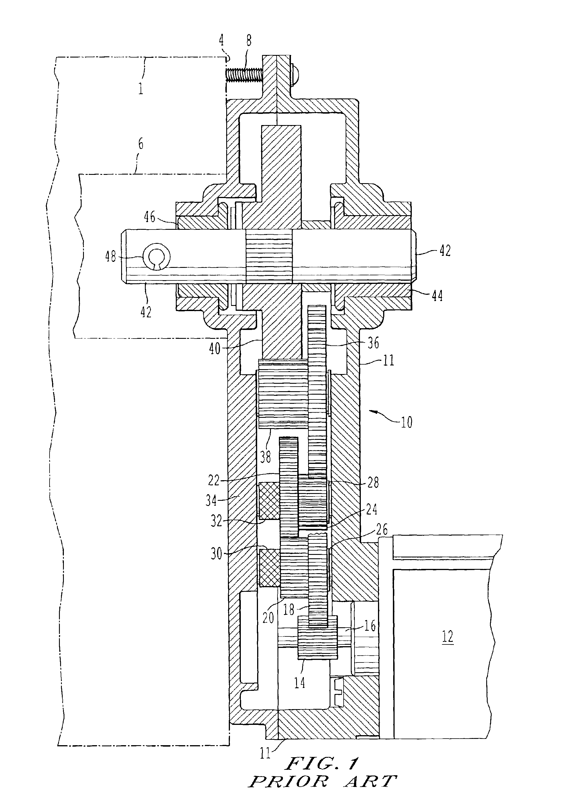
Thus, it remains a problem in the prior art to produce a high torque resistant and strong screwless gear box holding a reduction gear assembly inside.

Method used


Image

  • High torque resistant and strong screwless plastic gear box
  • High torque resistant and strong screwless plastic gear box
  • High torque resistant and strong screwless plastic gear box

Examples


Embodiment Construction

Referring now to the drawings, like reference numerals designate identical or corresponding parts throughout the several views.

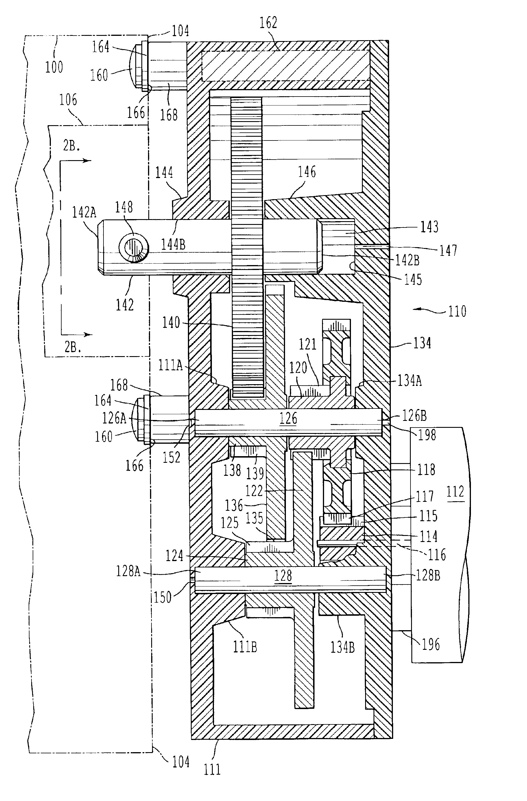
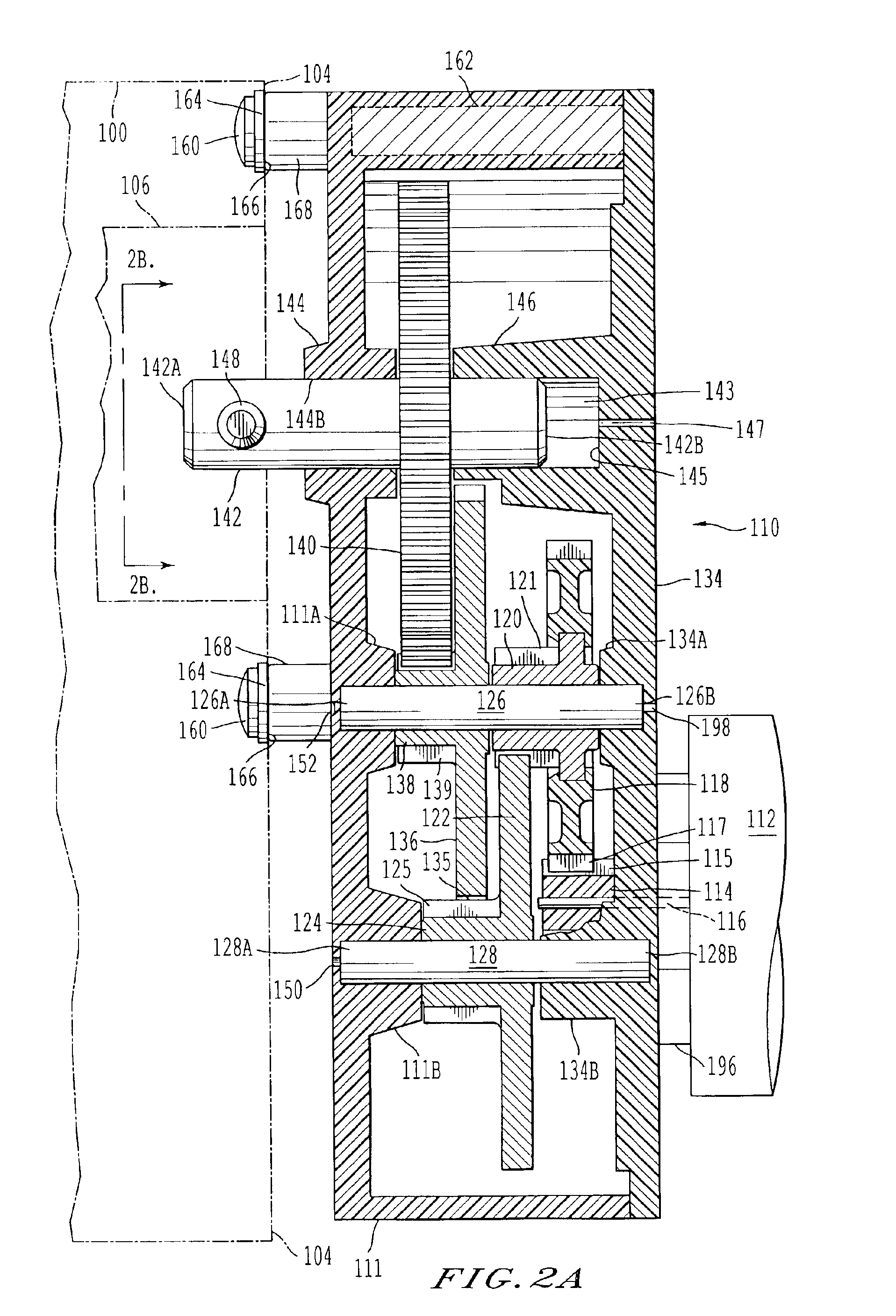
A cross-sectional view of the invention is shown in FIG. 2A. A gear box 110 has a main body 111 made of ABS plastic and is attached to a direct current (D.C.) motor 112 which turns a small input shaft 116 that carries and rotates a small input gear 114. Teeth 115 on the small input gear 114 mesh with and drive teeth 117 on a first central gear 118 which carries and rotates with a first pinion gear 120. This gear 120 has teeth 121 that, in turn, drive a second gear 122 which carries and rotates with a second pinion gear 124.

The small input gear 114 is made of hard plastic while the small input shaft 116 is made of steel. The first central gear 118 is made of plastic while the first pinion gear 120 is made of steel. Both the second gear 122 and the second pinion gear 124 are formed integrally of steel. Note that the first steel pinion gear 120 and the second s...


PUM


Abstract

A high torque resistant and strong screwless plastic gear box has a reduced thickness at its output shaft. The gear box and a reduction drive assembly therein may be used particularly, but not exclusively, in a slot machine with a spinning drum or hopper which holds coins or tokens to be released therefrom. The gear box includes a main body and a cover which is ultrasonically welded thereto. Locating posts, holding tubes, inner welding pads, outer surrounding tubes, and locating ribs are provided to weld the cover to the main body. Acoustical chambers are formed between outer walls and inner arcuate walls of the main body. The inner arcuate walls surround all of the shafts and gears inside the main body. This double-walled construction reduces noise and provides surprising mechanical strength. All of the gears are mounted on only three shafts secured between the main body and the cover. Four of the gears are stacked on a single central shaft and rotate in two pairs independently of each other.

Description

CROSS REFERENCE TO RELATED APPLICATIONThis application is related to U.S. Des. patent application Ser. No. 29 / 165,821 filed concurrently herewith.BACKGROUND OF THE INVENTION1. Field of the InventionThis invention relates to machine elements and mechanisms generally, but more particularly to small but strong plastic gear boxes with reduction drive assemblies inside.2. Description of the Related ArtU.S. Pat. No. 5,598,746 to Chen describes a transmission assembly having a plastic box and cover employing locating posts. U.S. Pat. No. 5,737,968 to Hardey et al. discloses a gear motor assembly with a three-part molded housing having plural cylindrical connector bosses which may be ultrasonically welded together. U.S. Pat. No. 4,825,727 to Komuro relates to a speed reducer having a gear mounting plate formed with ribs for noise reduction. These three prior art devices appear to be most relevant to the gear box of the present invention, in the applicant's view.U.S. Pat. No. 2,908,180 to Sw...

Claims


Application Information

Patent Timeline
IPC IPC(8): F16H57/02A63F5/04F16D1/06F16H1/20F16H57/028F16H57/032
CPCF16H57/028F16H57/032Y10T74/19651Y10T74/19684Y10T74/2186F16H2057/02095F16H57/02
Inventor TSERGAS, ATHANASE N.
Owner MOLON MOTOR COIL
Learn More