Damper unit and glove box device using the same

a technology of adamper unit and a glove box, which is applied in the direction of roofs, shock absorbers, wing accessories, etc., can solve the problems of poor assembly workability and high cost, and achieve the effect of high quality feeling

Inactive Publication Date: 2005-02-22
NIFCO INC
View PDF9 Cites 29 Cited by
  • Summary
  • Abstract
  • Description
  • Claims
  • Application Information

AI Technical Summary

Benefits of technology

[0028]With this configuration, when the glove box is opened, the damping force by the rotary damper acts, and the glove box main portion is opened slowly to thereby obtain high qual

Problems solved by technology

However, a large number of parts are required, resul

Method used


Image

  • Damper unit and glove box device using the same
  • Damper unit and glove box device using the same
  • Damper unit and glove box device using the same

Examples


Embodiment Construction

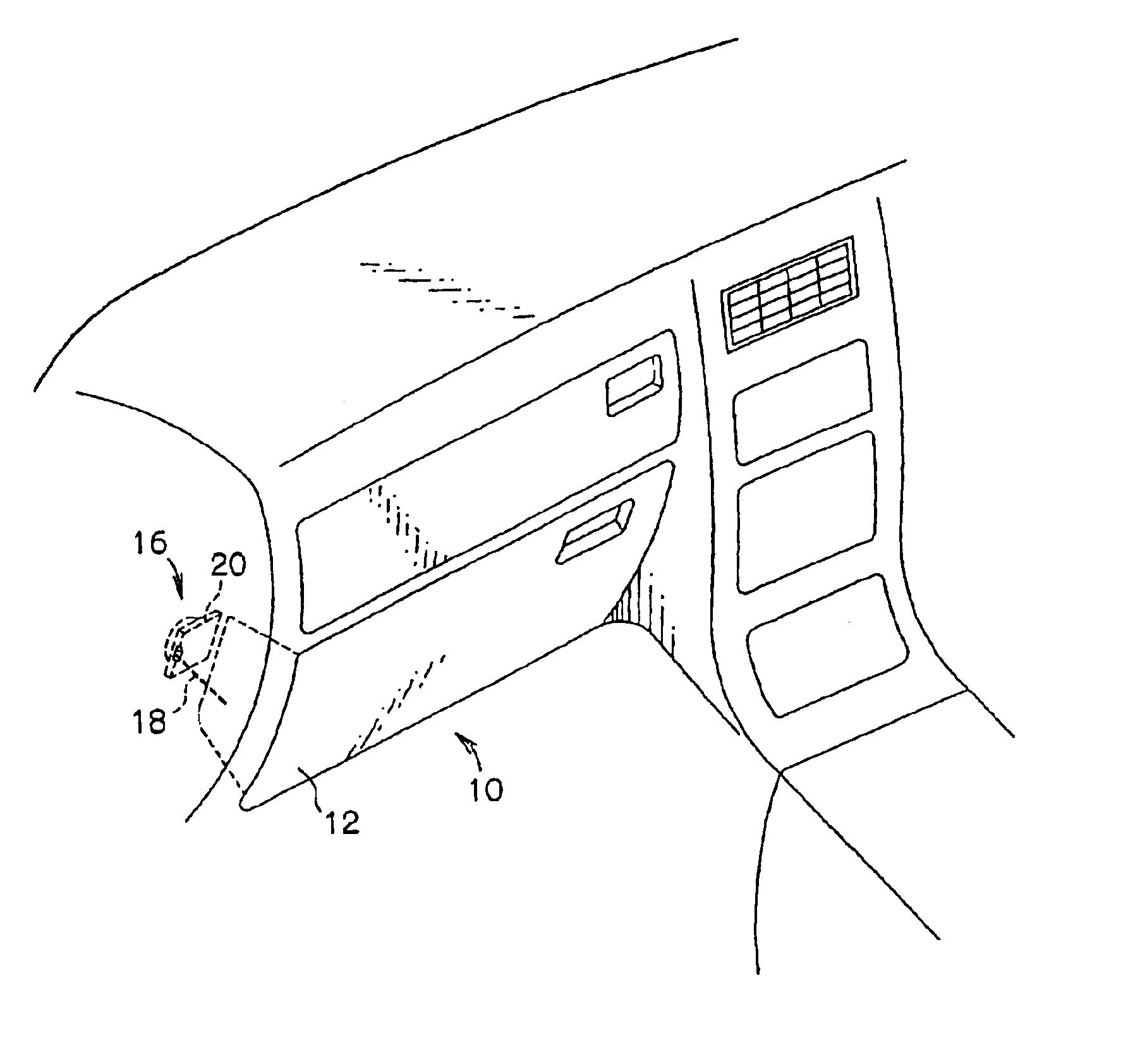
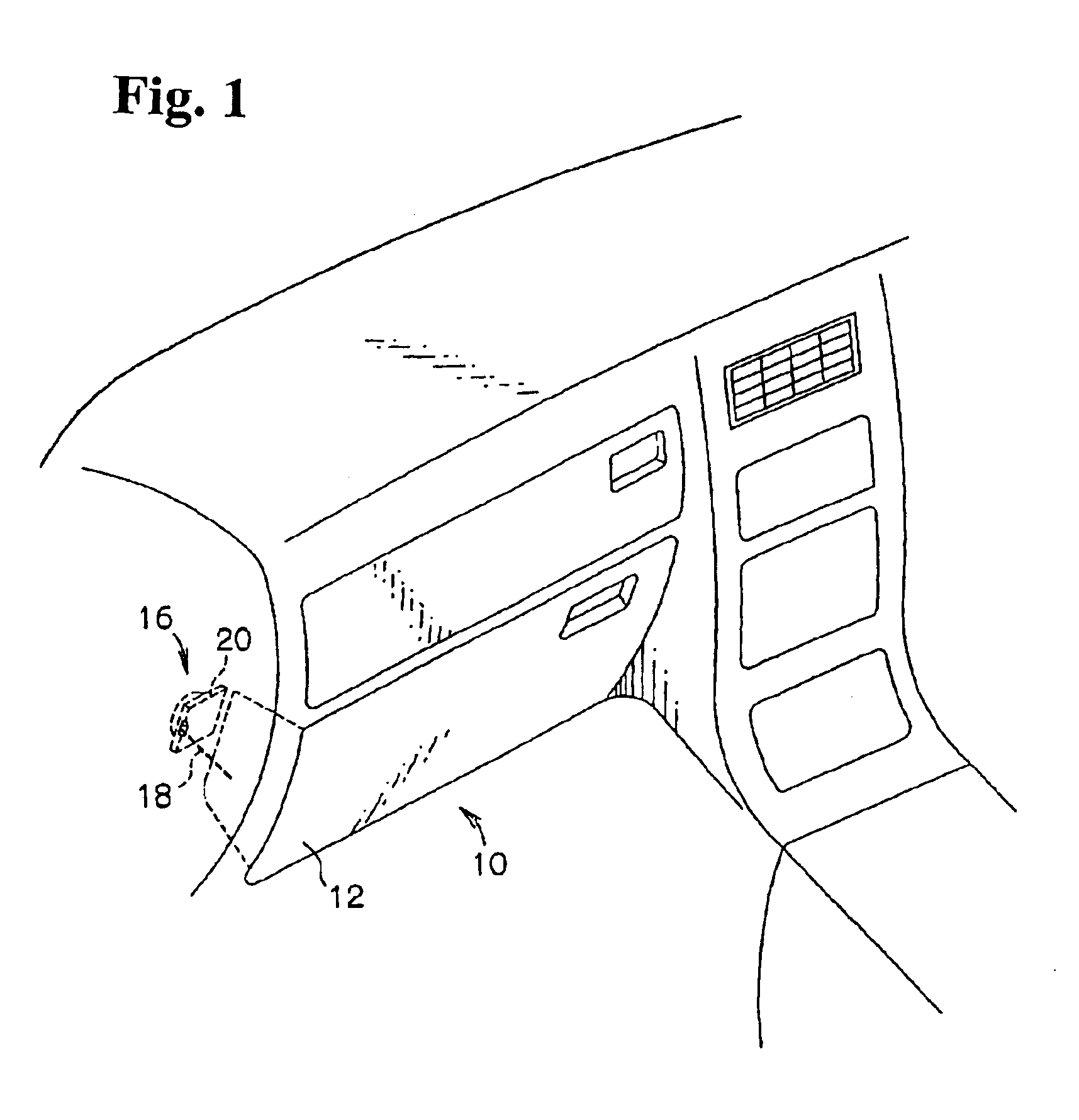
[0036]A glove box 10 and the like of a vehicle as shown in FIG. 1 is provided with a damper mechanism so that a glove box main portion 12 is not rapidly opened or an unpleasant percussive noise and the like is not generated upon opening and closing. A case 20 constituting a damper unit 16 is disposed on a car-body side, and a string 18 constituting the damper unit 16 is fixed to the glove box main portion 12 side.

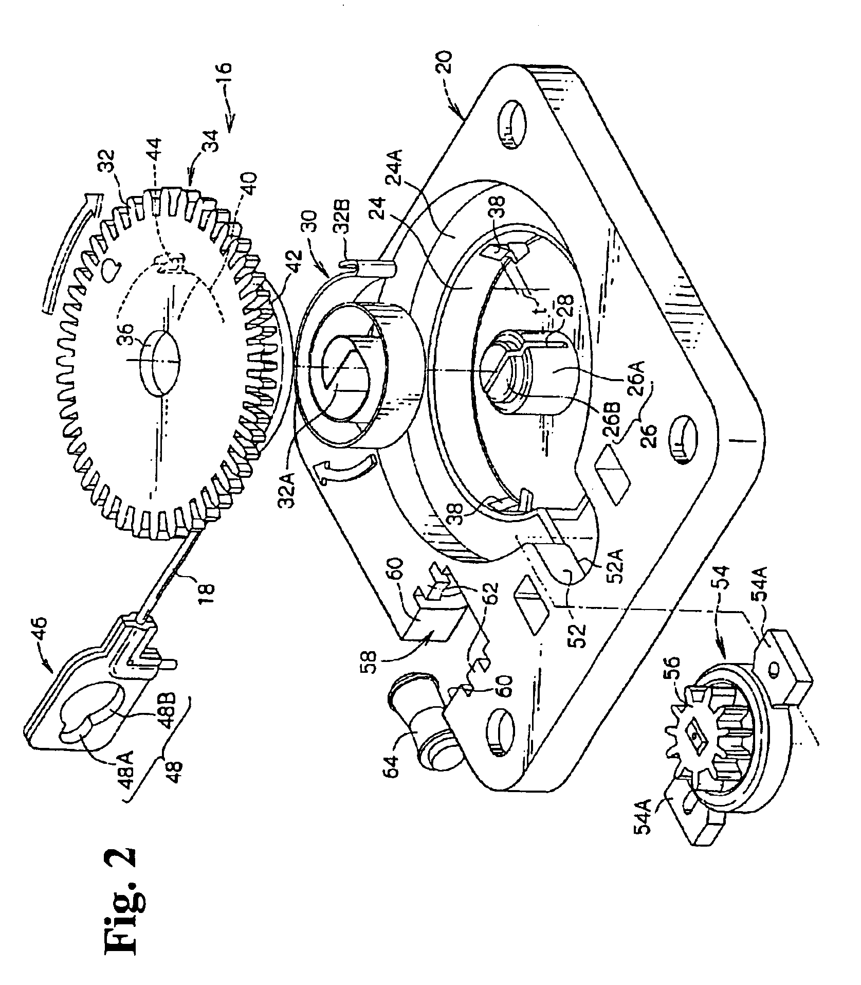
[0037]As shown in FIGS. 2 and 3, a substantially rectangular case 20 is provided to the damper unit 16 and fixed to an attaching seat 22 provided on the vehicle body (refer to FIG. 4). A receiving depression 24 is provided at the center portion of the case 20, and a boss 26 is formed at the center portion of the receiving depression 24.

[0038]The boss 26 includes a larger diameter portion 26A and a smaller diameter portion 26B. A notch portion 28 is formed to extend from the smaller diameter portion 26B to a base side of the larger diameter portion 26A to divide the boss int...


PUM


Abstract

A damper unit includes a gear having a core member projecting at a shaft core portion thereof and rotatably housed in a case, a string wound around the core member, a rotary damper engaging the gear for damping a rotational force of the gear, and a spring. One end of the spring is fixed to the case and the other end thereof is fixed to the core member so that an elastic force is accumulated when the string is pulled out.

Description

BACKGROUND OF THE INVENTION AND RELATED ART STATEMENT[0002]The invention relates to a damper unit and a glove box device using the damper unit.[0003]An automatic pull-out device 102 of a pull-out member 100 shown in FIGS. 6 and 7 includes a damper unit 104 (for example, as disclosed in Patent reference No.1). The damper unit 104 includes a unit case 106; a locking device 108 housed in the unit case 106; a low torque spring 110 for urging the pull-out member 100 in a pulling out direction; a winding reel 112 driven in a winding direction by the low torque spring 110; a long pulling rope 114 with one end thereof fixed to the winding reel 112; a rotary damper 116 for damping a rotation of the winding reel 112 at least in the winding direction; and a clutch mechanism 118 disposed between the winding reel 112 and the rotary damper 116 for shutting off transmission of the rotational force of the winding reel 112 in the pulling out direction.[0004]In the damper unit 104, when the pull-out ...

Claims


Application Information

Patent Timeline
IPC IPC(8): E05F1/14B60R7/06E05F3/14F16F7/00F16F9/12
CPCB60R7/06E05F3/14E05Y2201/21E05Y2201/254E05Y2201/266E05Y2900/538F16F7/00F16F9/12
Inventor KURACHI, KATSUHITOOKABAYASHI, SHUNSUKEHAYASHI, KENHAYASHI, HIROYUKIAMANO, MIKIHIRO
Owner NIFCO INC
Why Eureka
Try Eureka