
Golden rigid decorative member

a decorative member and rigid technology, applied in the field of decorative members, can solve the problems of easy control of color tone, prone to uneven color tone in production, abrasion resistance, etc., and achieve the effect of reducing the appearance quality due to flaws, suppressing abrasion or the like, and pale color

Active Publication Date: 2016-10-18
CITIZEN WATCH CO LTD
View PDF18 Cites 3 Cited by
  • Summary
  • Abstract
  • Description
  • Claims
  • Application Information

AI Technical Summary

Benefits of technology

The present invention provides a golden rigid decorative member that is highly resistant to wear and tear, and has a lightlweight, high-quality appearance. This invention also provides a method for stable production of the ornament.

Problems solved by technology

However, the alloy plating coating obtained by the wet plating method has had a color tone changed depending on the thickness of a coating, a current value, the shape of a base to be plated, and the like, it has not been easy to control the color tone, and therefore, unevenness in the color tone has been prone to occur in production.
Further, the gold alloy plating coating obtained by the wet plating method has had a low hardness, a Vickers hardness of 250 Hv or less in formation with a thickness of 10 μm, and has been poor in abrasion resistance, and therefore, the coating having a thickness of 30 μm or more has been generally formed and has been economically disadvantageous since gold which is a noble metal has been expensive.
The gold-tinted coating of Patent Literature 1 has had advantages that control of a color tone has been easy compared to conventional wet plating and abrasion resistance has been also improved; however, since a gold alloy has been used, the cost thereof has been still high, and it has not been able to be considered that the abrasion resistance has been sufficient.
However, the method of Patent Literature 2 has had a problem that since the coating has been formed using the target including an element of Group IVa elements of the periodical table and the target of a metal including Group Va elements or Group VIa elements, the two metals in the obtained coating have prevented a uniform alloy nitride from being formed, it has been difficult to control a color tone, productivity has been poor, and it has been impossible to stably form a pale golden coating with a high quality feel.

Method used


Image

  • Golden rigid decorative member
  • Golden rigid decorative member
  • Golden rigid decorative member

Examples


example 1

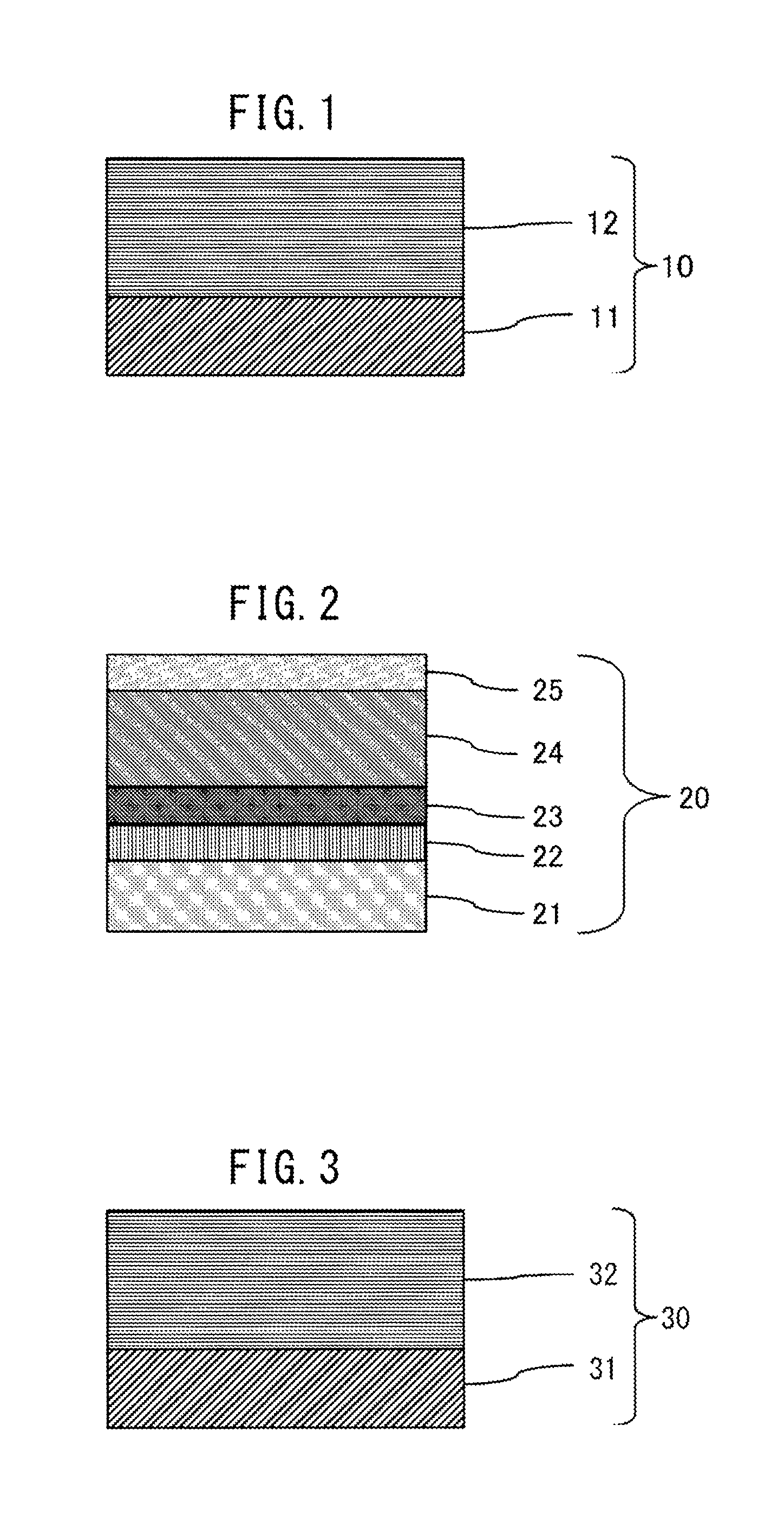
[0094]A sintered body with an alloy composition of 45 wt % Ti and 55 wt % Nb was used as a sputtering target. As illustrated in FIG. 3, an SUS316L material specified by JIS was used as a base 31, and a TiNb alloy nitride film 32 of 1.0 μm was formed on the base 31 by introducing 30 sccm of nitrogen gas into 105 sccm of argon gas by a sputtering method, to produce a golden rigid decorative member 30. The appearance color of the golden rigid decorative member 30 obtained thereby in Lab color space displaying exhibited L*: 83.15, a*: 1.07, and b*: 20.0, and the golden rigid decorative member 30 presented a pale gold color.

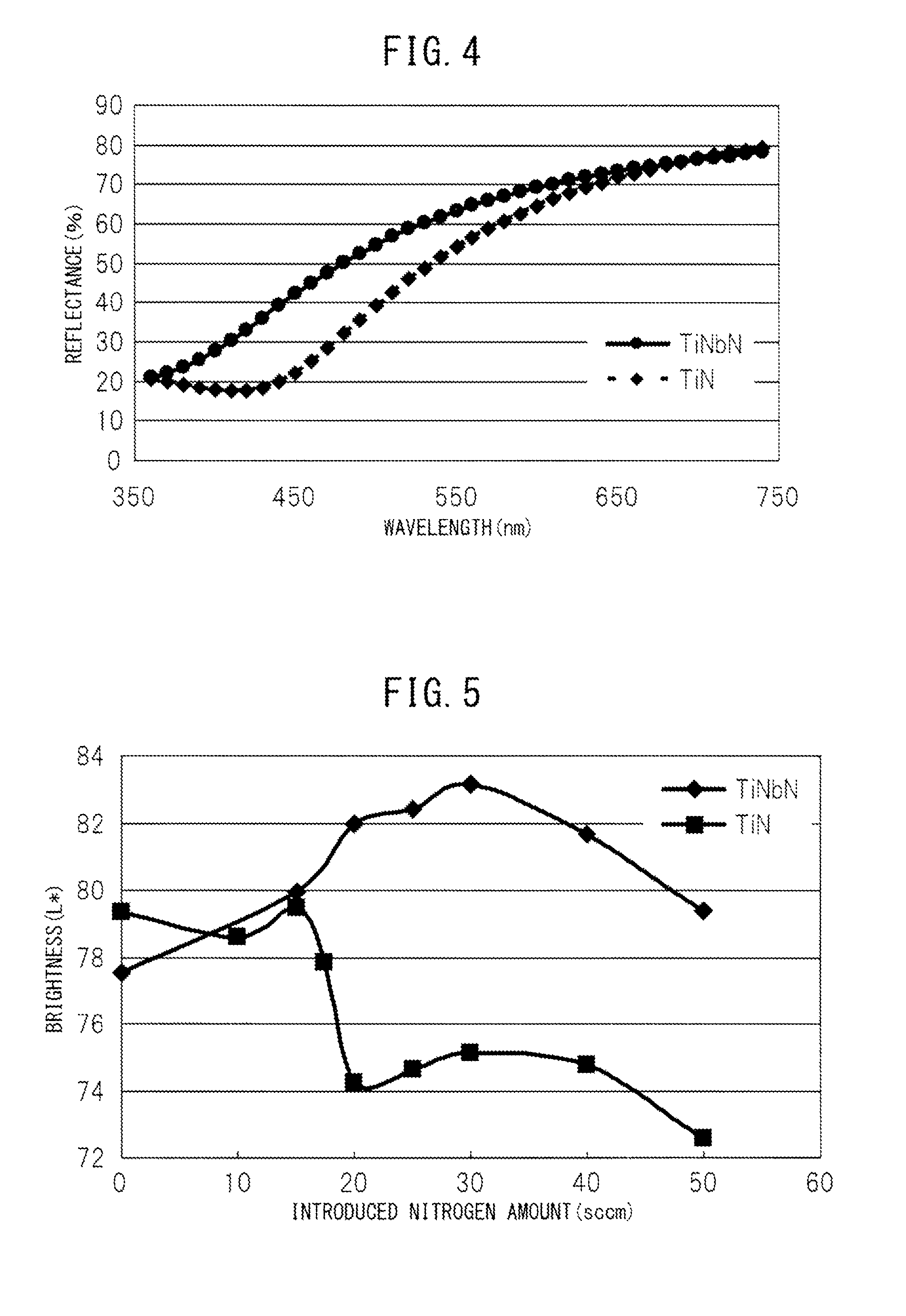
[0095]FIG. 4 represents a comparison of the reflectance properties of the TiNb alloy nitride film produced in Example 1 and the TiN film which is a common nitride presenting a gold color. It is found from FIG. 4 that the TiNb alloy nitride film produced in Example 1 has an obviously high reflectance and thus has high brightness.

[0096]FIG. 5 represents a comparison of ...

example 2

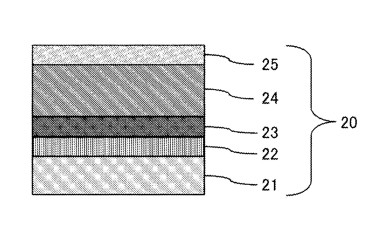
[0101]A sintered body with an alloy composition of 45 wt % Ti and 55 wt % Nb was used as a sputtering target. As illustrated in FIG. 10, an SUS316L material specified by JIS was used as a base 41, and an adhesion layer 42 of 0.1 μm including a lower oxide of a TiNb alloy was formed on the base 41 by a sputtering method. Thereafter, a nitrogen gas was increased in a gradient manner while introducing the minute amount of oxygen gas, whereby a gradient adhesion layer 43 with a TiNb alloy oxynitride film of 0.2 μm was formed. Thereafter, a thin-film abrasion-resistant layer 44 including a TiNb alloy nitride film of 1.5 μm was formed. Thereafter, a nitrogen gas was increased or decreased in a gradient manner, whereby a golden adjustment gradient layer 45 with the TiNb alloy nitride film of 0.1 μm was formed. The appearance color of the golden rigid decorative member 40 obtained in the present Example 2 in Lab color space displaying exhibited L*: 83.15, a*: 1.07, and b*: 20.0, and the TiN...

example 3

[0108]A sintered body with an alloy composition of 50 wt % Ti and 50 wt % Ta was used as a sputtering target. As illustrated in FIG. 13, an SUS316L material specified by JIS was used as a base 51, and a TiTa alloy nitride film 52 of 1.0 μm was formed on the base 51 by introducing 35 sccm of nitrogen gas into 105 sccm of argon gas by a sputtering method, to produce a golden rigid decorative member 50. The appearance color of the golden rigid decorative member 50 obtained in the present Example 3 in Lab color space displaying exhibited L*: 82.0, a*: 1.82, and b*: 22.84, and the TiTa alloy nitride film 52 presented a pale gold color.

[0109]FIG. 14 represents a comparison of the brightnesses of the films produced by changing the amount of nitrogen gas in the TiTa alloy nitride film and the TiN film. The brightness of the TiTa alloy nitride film is found to exhibit obviously high brightness compared to the TiN film when nitrogen is introduced to nitride the film.

[0110]FIG. 15 represents a...


PUM

PropertyMeasurementUnit
thicknessaaaaaaaaaa
thicknessaaaaaaaaaa
thicknessaaaaaaaaaa

Abstract

A golden rigid decorative member in which scratch resistance and abrasion resistance are significantly improved and deterioration of appearance quality due to a flaw, abrasion, or the like is suppressed, and which has a pale color with a high quality feel is stably provided. A single layer or several layers of a coating including a reaction compound of an alloy of Ti and one or two or more metals selected from Nb, Ta, and V, and of one or two non-metallic elements mainly including nitrogen and selected from carbon and oxygen are stacked on a base.

Description

TECHNICAL FIELD[0001]The present invention relates to decorative members having metallic colors for exterior parts of watches, personal ornaments such as glasses and accessories, decorative trim, and the like, and sporting goods, and particularly relates to a golden rigid decorative member with a pale color that is highly bright and has a high quality feel, and is excellent in scratch resistance, abrasion resistance, and an anticorrosion property for a long period.BACKGROUND ART[0002]A pale gold-tinted plating coating has been conventionally formed on the outermost layer of an abrasion-resistant layer for improving the scratch resistance of exterior parts, personal ornaments such as glasses, accessories, and watches, decorative trims, sporting goods, and the like in order to make an appearance with a high quality feel. The pale gold-tinted plating coating has been often formed by a wet plating method using a gold alloy of gold, and nickel, copper, silver, cobalt, cadmium, tin, or th...

Claims


Application Information

Patent Timeline
Patent Type & Authority Patents(United States)
IPC IPC(8): C23C14/06G04B37/22C23C14/14A44C27/00C23C14/34C23C14/02C23C14/00C09D1/00
CPCC09D1/00A44C27/007C23C14/0015C23C14/0036C23C14/025C23C14/0641C23C14/0676C23C14/14C23C14/3414G04B37/221A44C27/005Y10T428/265G04B37/22
Inventor TAKAZAKI, KOUTAROU
Owner CITIZEN WATCH CO LTD
Learn More