Ring illuminator

a technology of illuminating and ring, which is applied in the field of ring illuminating, can solve the problems of large power consumption, inability to clearly detect the shadows of the edge portions, and short lifetime and/or slow response rate when controlling the lighting intensity and upon being turned, so as to enhance the illumination efficiency of the object and enhance the accuracy of image detection

Inactive Publication Date: 2005-02-22
MITUTOYO CORP
View PDF8 Cites 45 Cited by
  • Summary
  • Abstract
  • Description
  • Claims
  • Application Information

AI Technical Summary

Benefits of technology

This invention separately provides a ring illuminator that can sufficiently enhance the accuracy of the image detection.
In various exemplary embodiments, using the torus-shaped lens, which is a general-purpose optical element, the ring illuminator can be manufactured at a low cost. At the same time, by using a lens having high transmissivity and high accuracy, the transmission loss of the combined illumination light can be suppressed to a small amount. Likewise it is possible to accurately focus the combined illumination light over an illumination range to further enhance the illumination efficiency. Further, in various exemplary embodiments, the objective lens or the like which constitute the optical system can penetrate the ring illuminator through the hole formed in the center portion of the torus-shaped lens. Accordingly, the light reflected from the object to be measured can reach the objective lens or the like without being interrupted. Hence, the measurement of the object to be measured can be surely performed.

Problems solved by technology

Accordingly, when measuring an object to be measured having a complicated shape, such as, for example, a step-like object to be measured having a large number of edge portions, shadows of the edge portions often cannot be clearly detected.
However, the halogen lamp or the like also has disadvantages, including a large power consumption, a short lifetime and / or a slow response rate when controlling the lighting intensity and upon being turned on and off.
However, this necessitates a large number of lamps or shutters and the structure becomes complicated.
Hence, the illuminator becomes overly large and the manufacturing cost increases.
Hence, the illumination efficiency is not sufficiently enhanced.
However, this does not correct the above-mentioned intrinsic divergence angles of the light emitting diodes.
Hence, it is difficult to achieve a remarkable enhancement of illumination efficiency even with this technique.
This results in the illumination light spreading, which lowers the illumination efficiency.
Further, to maintain the illumination efficiency, the operable distance cannot be changed.
Hence, it is difficult to obtain an optimum illumination light for every object to be measured.
However, in these known ring illuminators, in the same manner as the above-mentioned 417 patent, due to divergence angles of light beams that radiate from respective ones of the light emitting diodes, the illumination efficiency is not sufficiently enhanced.
Consequently, the structure of the illuminator becomes complicated.
However, in the ring illuminators discussed previously, since the illumination efficiency is low, it is necessary to arrange a large number of light emitting diodes.
As a result, the ring illuminator becomes overly large and the manufacturing cost increases.
Hence, the hue of the generated illumination light is not uniform across the object.
Consequently, an image of sufficiently high accuracy cannot be obtained.

Method used


Image

  • Ring illuminator
  • Ring illuminator
  • Ring illuminator

Examples


Embodiment Construction

Various exemplary embodiments of a ring illuminator according to this invention are explained in detail in conjunction with various drawings figures. In the following explanation, identical or substantially similar constitutional elements are given the same numerals and their explanation is omitted or simplified.

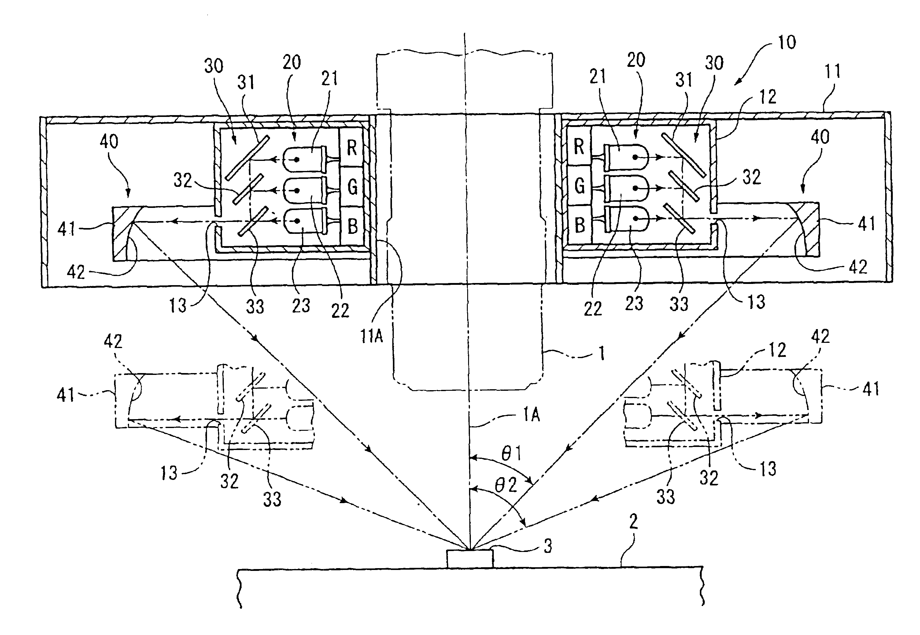
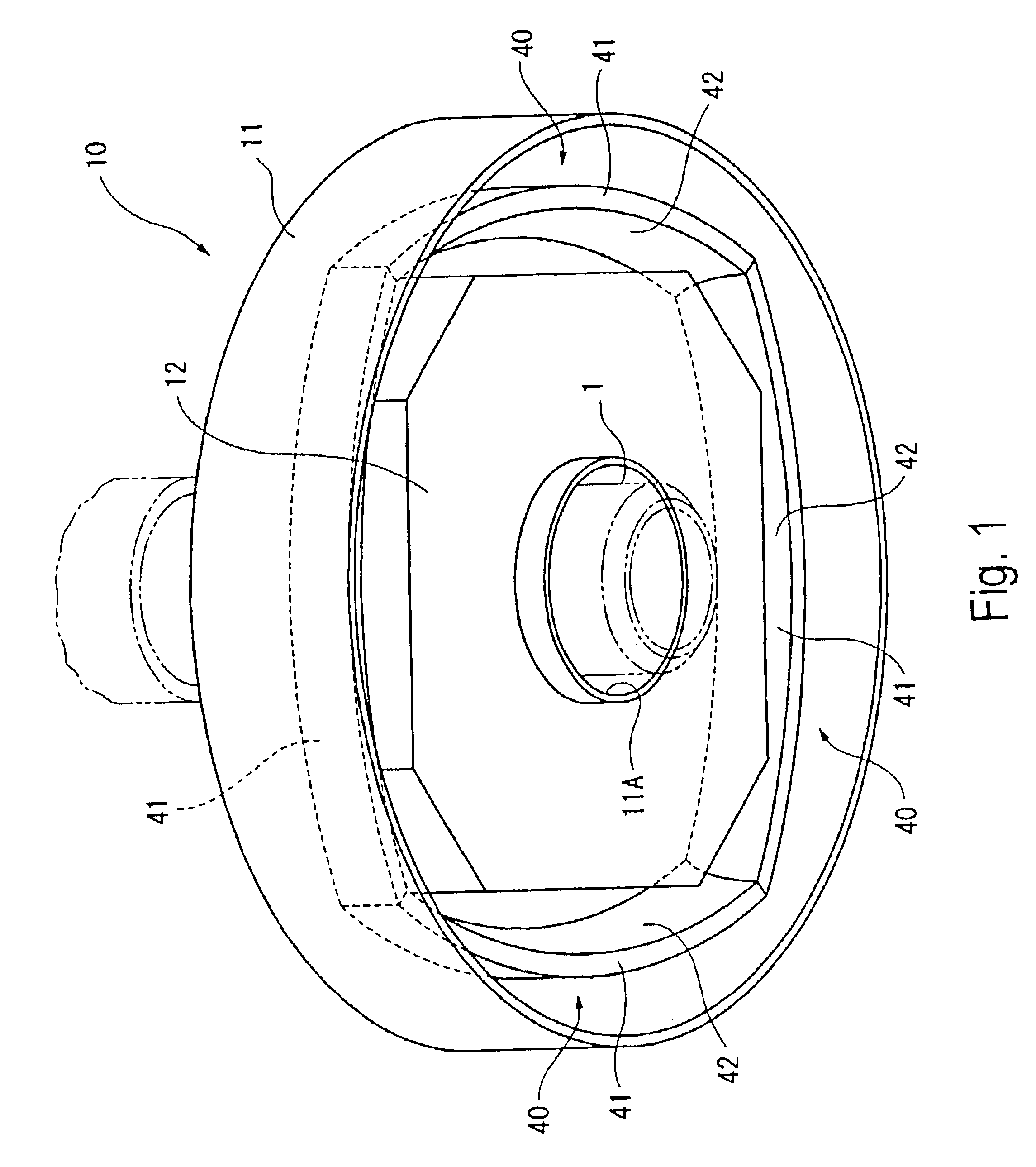
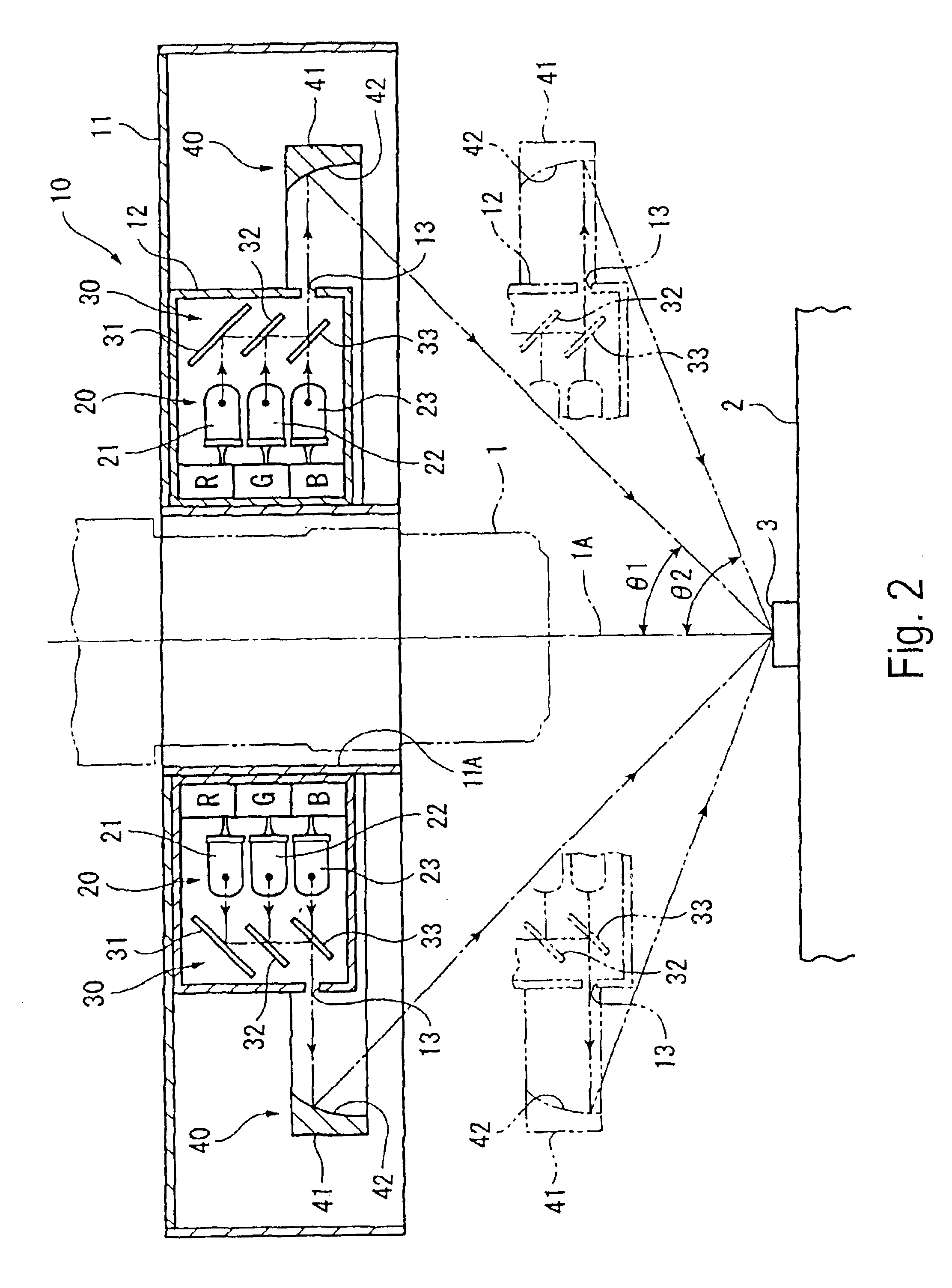
A first exemplary embodiment of ring illuminator 10 according to this invention is shown in FIG. 1 to FIG. 3. Second and third exemplary embodiments, of ring illuminators 50 and 60 according to this invention are respectively shown in FIG. 4 and FIG. 5.

FIG. 1 is an overall perspective view of the ring illuminator 10, FIG. 2 is a cross-sectional view of the ring illuminator 10 and FIG. 3 is a bottom view of the ring illuminator 10 with a part in cross section. In FIG. 1 to FIG. 3, the ring illuminator 10 illuminates an object to be measured 3 (i.e., a work piece), which is placed on a measuring base console 2 of an image measuring device (not shown in the drawing). The illumi...


PUM

PropertyMeasurementUnit
divergence angleaaaaaaaaaa
degree of freedomaaaaaaaaaa

Abstract

A plurality of light emitting elements comprise a number of groups having light emitting colors different from each other. The light emitting element groups are arranged in ring shapes about an optical axis of an optical system in a plane or planes substantially orthogonal to the optical axis. A combining unit combines radiation light beams of different light emitting colors to generate illumination light having a given hue. The combining unit is provided downstream of the light emitting elements along a light emitting direction. A focusing unit focuses the illumination light in the direction toward the optical axis and is provided downstream of the combining unit. Accordingly, it is possible to direct illumination light having uniform and non-irregular hue, the hue corresponding to a surface color of an object to be measured, to the object to be measured.

Description

BACKGROUND OF THE INVENTION1. Field of InventionThis invention relates to a ring illuminator for an optical measuring apparatus.2. Description of Related ArtIllumination of an object to be measured plays an extremely important role in obtaining a clear image of the object to be measured in an optical microscope. The illumination is important when attempting to optically focus on a portion of the object to be measured. The illumination is also important when capturing an image of the portion using an image processing type measuring apparatus such as a measuring microscope, a tool microscope, a projector or a three-dimensional image measuring apparatus. These devices are particularly useful in inspecting and measuring a shape and a size of the object to be measured based on the captured image of the object to be measured.Known illumination methods used with such image processing type measuring apparatus or the like include a vertical downward radiation illumination method, which radia...

Claims


Application Information

Patent Timeline
Patent Type & Authority Patents(United States)
IPC IPC(8): G01N21/88G02B27/10G02B21/08G02B21/06F21V7/00G01B11/00G01N21/01G01N21/27G01N21/84G03B15/00G03B15/02G03B15/05
CPCG01N21/8806G02B21/084G02B27/145F21V7/0008F21Y2101/02Y10S362/80G01N2201/0627G01N2201/062F21Y2115/10
Inventor SHIMOKAWA, SEIJINAGAHAMA, TATSUYAOBATA, KUNIAKIMATSUBARA, HIROTAKA
Owner MITUTOYO CORP
Why Eureka
Try Eureka