Device for providing microclimate control

a microclimate and control device technology, applied in the field of providing microclimate control devices, can solve the problems of low cooling density of phase-change materials for direct cooling of people, ineffective pcms, and individual's often significant perspiration, so as to increase the capacity of desiccant, enhance the water extraction capability of the device, and reduce the amount of heat transferred

Inactive Publication Date: 2005-02-22
NANOPORE INC
View PDF38 Cites 57 Cited by
  • Summary
  • Abstract
  • Description
  • Claims
  • Application Information

AI Technical Summary

Benefits of technology

According to one embodiment, a device for adsorbing water vapor from a gas stream is provided. The device includes a gas stream inlet and a gas stream outlet and at least a first flow channel disposed between the inlet and the outlet. A desiccant is in vapor communication with the first flow channel and a phase-change material is in thermal communication with the desiccant. The device also includes means for moving the gas stream from the inlet to the outlet. As the gas stream moves from the inlet to the outlet, through the flow channel, the desiccant adsorbs water vapor from the gas stream. The phase-change material advantageously extracts heat that is generated by the desiccant during adsorption, thereby increasing the capacity of the desiccant and also reducing the amount of heat transferred to the gas stream.
The device can include a plurality of flow channels to enhance the water extraction capability of the device. The desiccant can be disposed within the flow channels or the desiccant can be a rigid structure that defines at least a first wall of the flow channel. The device can be encapsulated in an impermeable envelope before activation of the device. The means for moving the gas stream can include, for example, a fan.

Problems solved by technology

However, phase-change materials have a relatively low cooling density for direct cooling of a person and typically have a phase change temperature significantly below body temperature (−37° C.).
Moreover, PCMs are not effective where there is a possibility of vapor build up within the garment.
Similar suits are also often used in an uncomfortably hot atmosphere, such as steel mills and deep mines and, as a result, the individual will often perspire significantly.
The resulting perspiration can cause a rapid buildup of water vapor within the suit which lowers the user's rate of heat rejection.
In the case of a sealed suit, the build-up of water vapor can cause visibility problems from condensation of the vapor on the user's visor.
Physical and physiological discomfort may also result from the increased temperature of the suit and the build-up of perspiration on the user's skin and clothing.
Aside from the impracticality of maintaining temperatures suitable to maintain the ice within the garment, ice has a low cooling density and has logistical disadvantages in that the ice must be available to the user at or near the hostile environment.
Ice also cannot remove water vapor from the garment.
In fact, as the ice melts, it will likely contribute to the humidification of the garment.
The use of ice also suffers in that the user cannot control the rate of cooling within the garment.

Method used


Image

  • Device for providing microclimate control
  • Device for providing microclimate control
  • Device for providing microclimate control

Examples


example 1

Modified Carbon with PCM

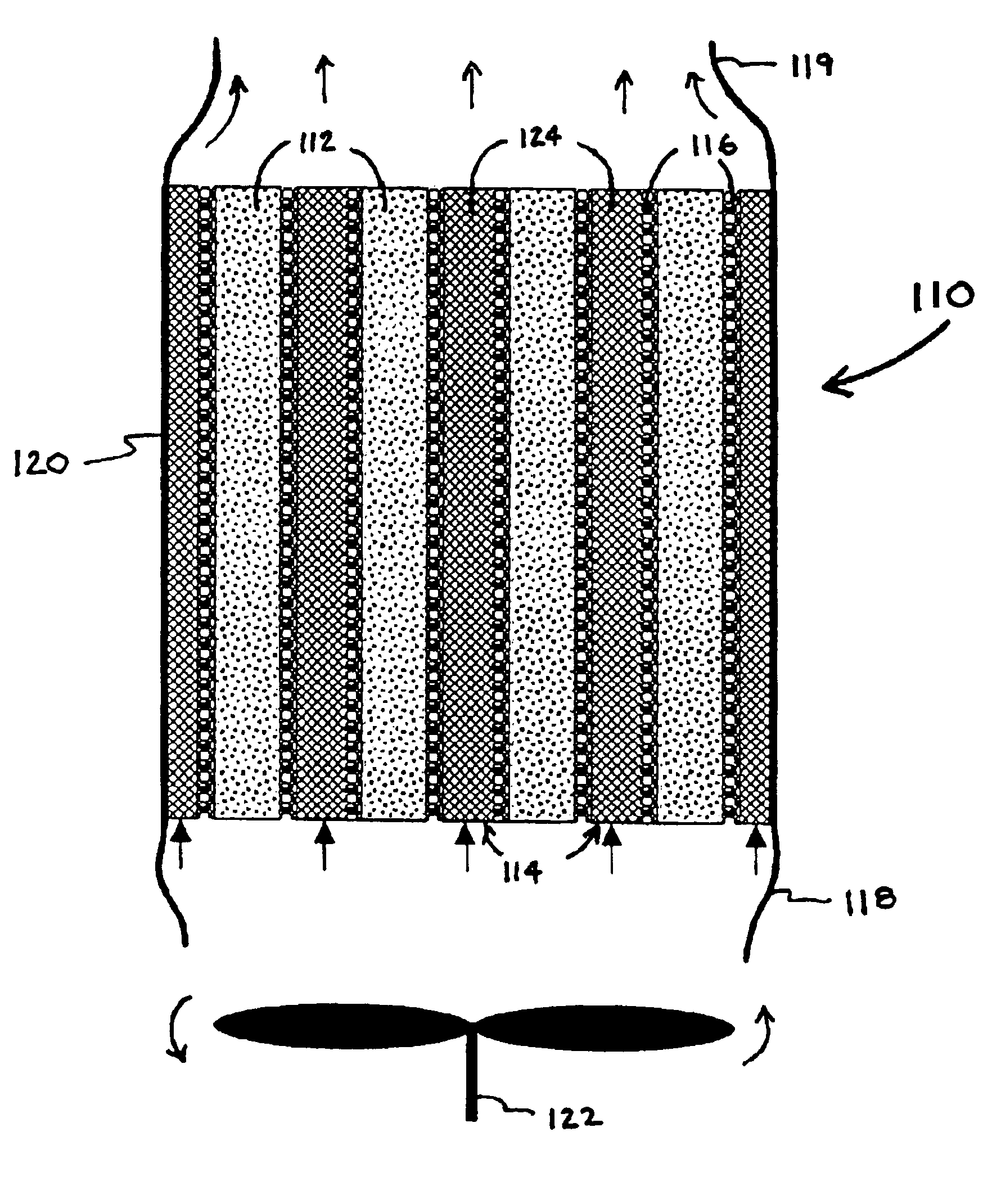
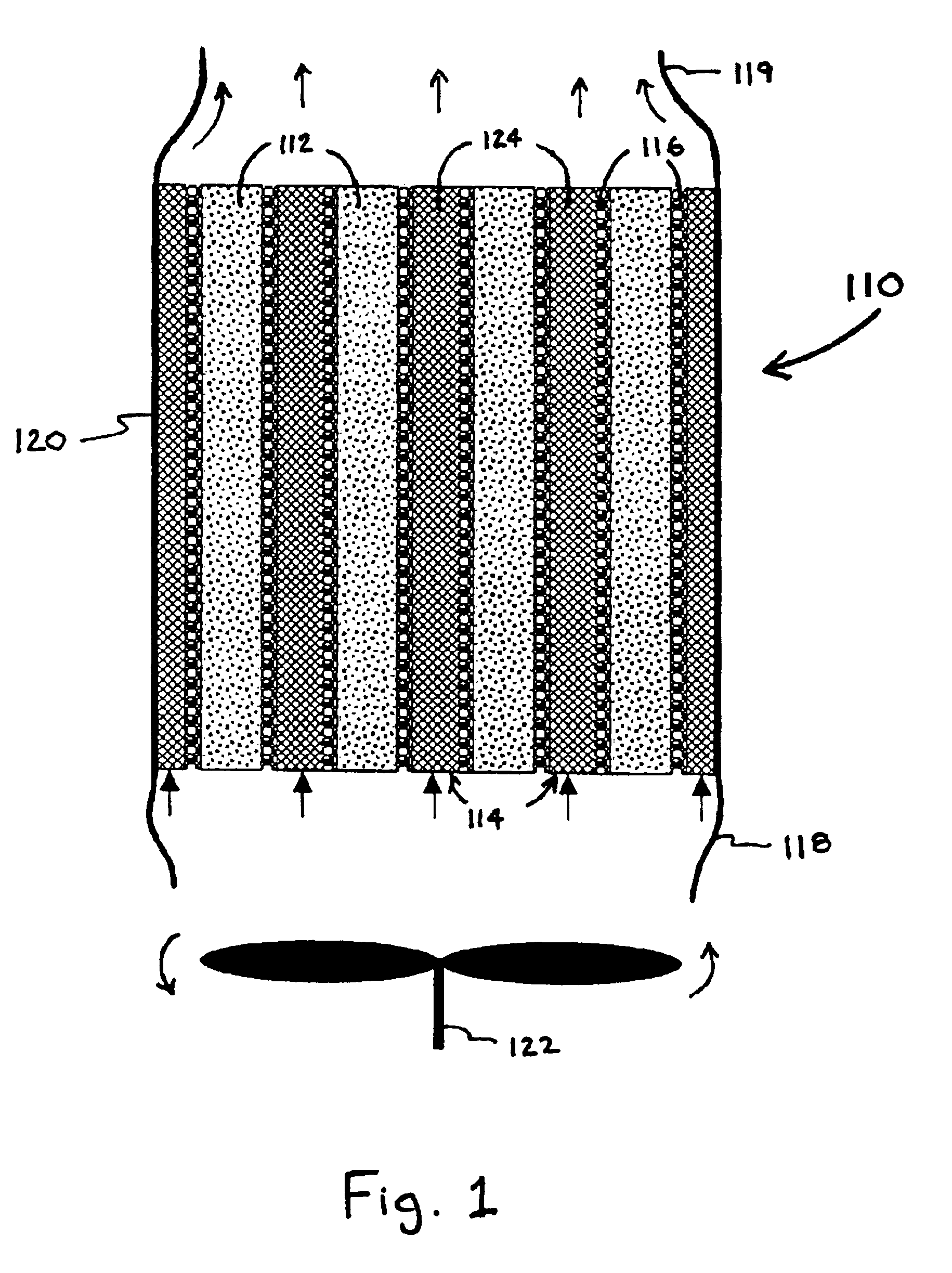
This device includes 12 layers of modified carbon, 7 PCM bags, and 12 layers of flow channel material. All layers are a finished size of 10 cm×15 cm. The carbon sheets each weigh about 7.2 grams, 50% of which is carbon. For a 50% LiCl / 50% carbon loading, a total of 3.6 grams of LiCl is impregnated into each sheet. The 3.6 grams of LiCl is dissolved into 8.5 ml of 50% deionized water 150% methanol. The carbon sheet is pre-treated with 0.5 ml of 50% deionized water 150% methanol on each side. While the sheet is still moist, a total of 3 ml of the salt / water / alcohol mixture is wicked into the sheet. Then the sheet is placed in a 50° C. oven for at least two hours to dry. The sheet is then wicked a second time (after pre-treating) with about 3 ml of salt / water / alcohol mixture. The sheet is again dried at 50° C. for at least two hours, then again pre-treated and wicked with the remaining solution. The sheet is now ready for final drying at 70° C. in a vacuum oven ...

example 2

Modified Carbon with No PCM

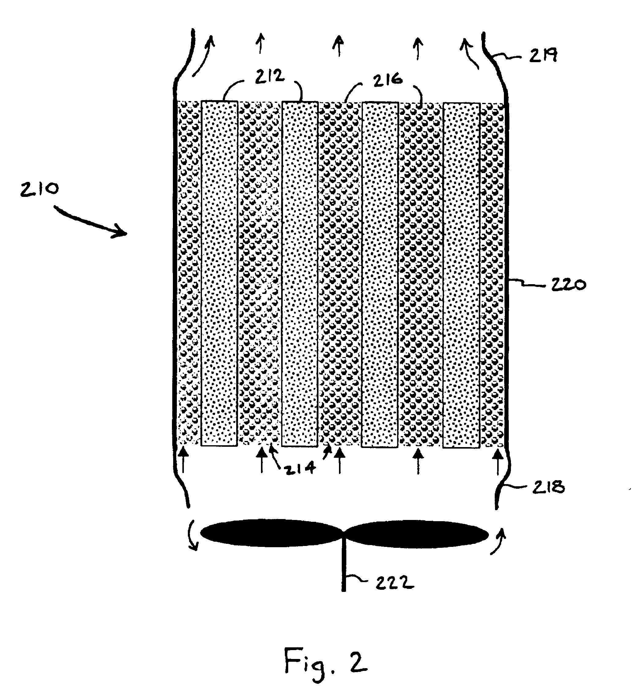
This device has 12 layers of modified carbon and 12 layers of flow channel material. All layers are a finished size of 10 cm×15 cm. The carbon sheets each weigh about 7.2 grams, 50% of which is carbon. For a 50% LiCl 150% carbon loading, a total of 3.6 grams of LiCl is impregnated into each sheet. The 3.6 grams of LiCl is dissolved into 8.5 ml of 50% deionized water / 50% methanol. The carbon sheet is pre-treated with 0.5 ml of 50% deionized water / 50% methanol on each side. While the sheet is still moist, a total of 3 ml of the salt / water / alcohol mixture is wicked into the sheet. Then the sheet is placed in a 50° C. oven for at least two hours to dry. The sheet is then wicked a second time (after pre-treating) with about 3 ml of salt / water / alcohol mixture. The sheet is again dried at 50° C. for at least two hours, then again pre-treated and wicked with the remaining solution. The sheet is now ready for its final drying at 70° C. in a vacuum oven overnight. T...

example 3

Unmodified Carbon with PCM

This device includes 12 layers of unmodified carbon, 7 PCM bags, and 12 layers of flow channel material. All layers are a finished size of 10 cm×15 cm. The carbon sheets each weigh about 7.2 grams, 50% of which is carbon. The sheets are dried at 70° C. overnight in a vacuum oven to remove water. The PCM bags are made of Rexam. The measurements from inside seal to inside seal are about 15 cm×15 cm. Five of these bags are filled with 106 grams of sodium sulfate decahydrate Na2SO4.10H2O. The other two bags are filled with 53 grams of the PCM for the sidewall pieces. Twelve pieces of flow channel material are cut and arranged in pairs so that the weave on one layer is perpendicular the weave on the second layer. The carbon sheets, PCM bags, and flow channel material are assembled under a nitrogen environment to prevent the carbon sheets from adsorbing water. Two Lexan polycarbonate pieces are placed on the top and the bottom of the stack and are bound together ...


PUM

PropertyMeasurementUnit
transition temperatureaaaaaaaaaa
volumetric energy densityaaaaaaaaaa
temperatureaaaaaaaaaa

Abstract

A device for adsorbing water vapor from a gas stream. The device can be incorporated with an enclosure or garment in such a manner so as to enable water vapor to be adsorbed, thereby decreasing the relative humidity in the micrlimate surrounding the user. The water adsorption device is light-weight, has a high mass and volumetric energy capacity. A desiccant material is included within the water adsorption device to adsorb water vapor and a phase-change material is located in thermal communication with the desiccant to increase the loading capacity of the desiccant and maintain a cool gas stream by extracting the heat of adsorption from the desiccant.

Description

BACKGROUND OF THE INVENTION1. Field of the InventionThe present invention relates to a device which dehumidifies a gas stream and has a relatively high water adsorption capacity. The device can be incorporated into a garment or enclosure and is adapted to cool the user of a garment by evaporative cooling and provide microclimate control to an enclosure.2. Background of the InventionGarments designed to cool users while they are wearing the garment are known in the art. Typically, cooling devices and / or materials are incorporated into a portion of the garment to achieve such cooling. For example, U.S. Pat. No. 6,298,907 by Colvin et al. discloses a vest incorporating micropouches which contain a phase-change material (“PCM”) to cool a person wearing the vest. The micropouches are in thermal communication with the person wearing the vest and the PCM is selected such that as the body temperature of the person increases, the phase-change materials will change from a solid to a liquid ph...

Claims


Application Information

Patent Timeline
Patent Type & Authority Patents(United States)
IPC IPC(8): B01D53/26B01D53/04
CPCB01D53/0415B01D53/261B01D53/02A41D13/0056Y10S165/902B01D53/0438B01D2253/102B01D2253/104B01D2253/108B01D2253/112B01D2253/25B01D2257/80B01D2259/4148B01D2259/4541B01D2259/4583B01D2259/657
Inventor SMITH, DOUGLAS M.RODERICK, KEVIN H.
Owner NANOPORE INC
Why Eureka
Try Eureka