
Thermally sensitive, multilayer imageable element

a multi-layer, thermal imageable technology, applied in the field of lithographic printing, can solve the problems of thermal imageable elements sensitive to mechanical damage, top layer of multi-layer, easy scuffing or scratching,

Inactive Publication Date: 2005-02-22
KODAK POLYCHROME GRAPHICS
View PDF16 Cites 30 Cited by
  • Summary
  • Abstract
  • Description
  • Claims
  • Application Information

AI Technical Summary

Benefits of technology

In another aspect, the element additionally comprises a photothermal conversion material. In another aspect, the invention is a method for forming an image by imagin

Problems solved by technology

The top layer of a multi-layer, thermally imageable element is sensitive to mechanical damage.
It may, for example, be easily scuffed or scratched away when the imageable element is transported with suction cups in a platesetter or when it is transported to a customer location.

Method used


Image

  • Thermally sensitive, multilayer imageable element
  • Thermally sensitive, multilayer imageable element
  • Thermally sensitive, multilayer imageable element

Examples


examples

In the Examples, “coating solution” refers to the mixture of solvent or solvents and additives coated, even though some of the additives may be in suspension rather than in solution, and “total solids” refers to the total amount of nonvolatile material in the coating solution even though some of the additives may be nonvolatile liquids at ambient temperature. Except where indicated, the indicated percentages are percentages by weight based on the total solids in the coating solution. “Molecular weight” refers to weight average molecular weight measured by size exclusion chromatography.

Glossary956 DeveloperSolvent-based (phenoxyethanol) alkaline developer(Kodak Polychrome Graphics, Norwalk, CT, USA)2531-35Novolac resin, 50% m-cresol / 50% p-cresol; MW 5,000(Borden Chemical, Louisville, KY, USA)2531-36Novolac resin, 50% m-cresol / 50% p-cresol; MW 9,900(Borden Chemical, Louisville, KY, USA)2539-22Novolac resin, 50% m-cresol / 50% p-cresol; MW 14,000(Borden Chemical, Louisville, KY, USA)2539...

examples 1-6

This example shows that novolac resins with increasing p-cresol content have improved developer resistance and, hence, increased ability to withstand scuffing over a m-cresol-only novolac resin.

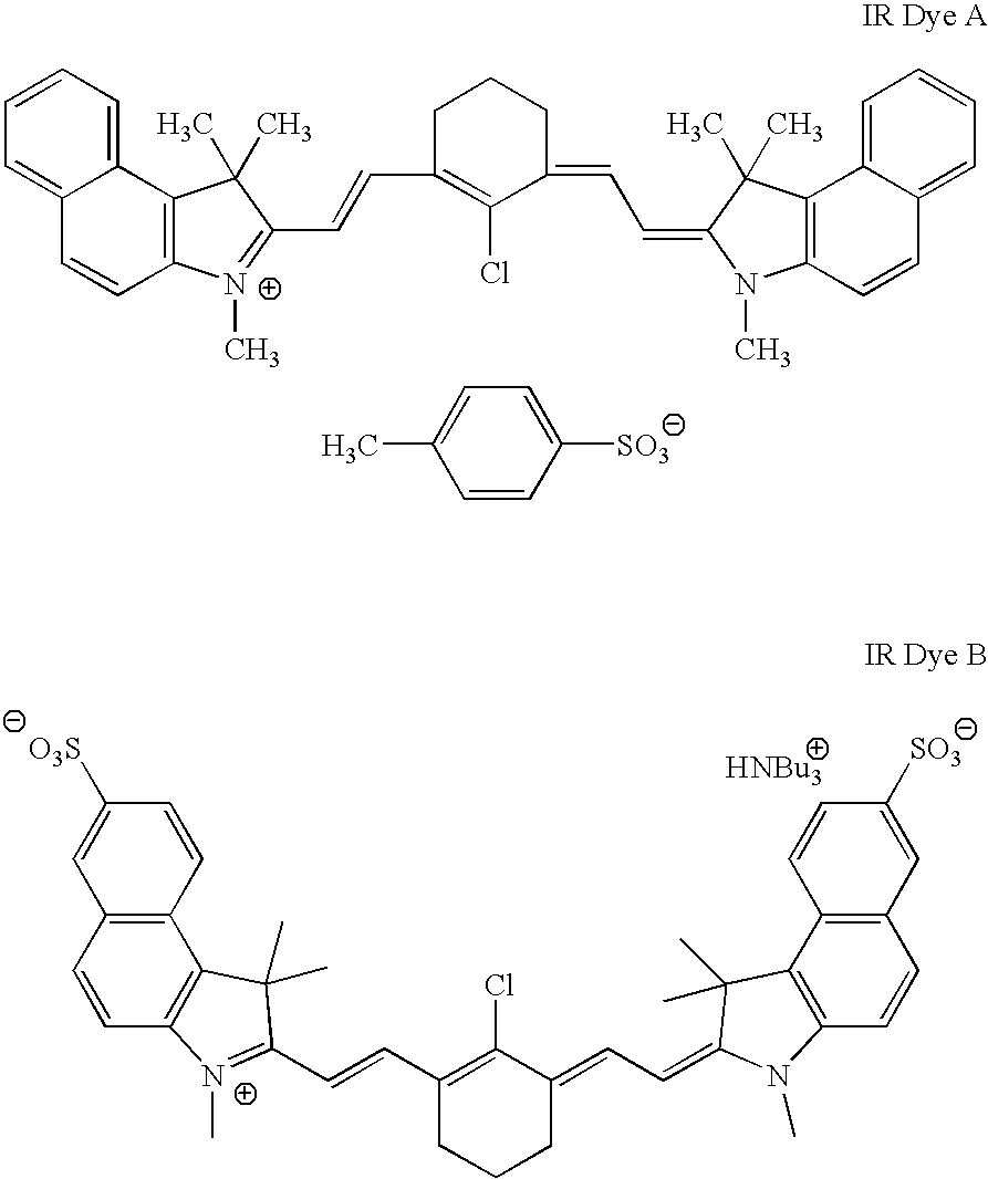
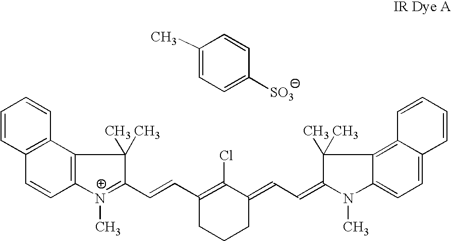
Underlayer A coating solution containing 85 parts by weight of binder A and 15 parts by weight of IR Dye A in 15:20:5:60 (w:w) butyrolactone:methyl ethyl ketone:water:1-methoxypropan-2-ol were coated onto substrate A using a wire wound bar. The resulting element comprising the underlayer and the substrate was dried at 100° C. for 90 seconds. The coating weight of the resulting underlayer was of 2.0 g / m2.

Top Layer Coating solutions containing 96.3 parts by weight of the novolac resin, and 3.7 parts by weight of ethyl violet in diethyl ketone were coated onto the underlayer using a wire wound bar. The coating weight of the resulting top layer was of 0.7 g / m2. The resulting imageable elements were dried at 100° C. for 90 seconds. The novolac resins used are shown in Table 1.

Each of the imageable...

examples 7-9

These examples show that novolac resins with increasing molecular weight have improved developer resistance and, hence, increased ability to withstand scuffing.

The procedure of Examples 1-6 was repeated except that the novolac resins indicated in Table 2 were used. Each of the resulting imageable elements was evaluated by the drop test. The results are shown in Table 2.

TABLE 2ExampleResin% p-cresolMWDrop Testa7N130%13,000360 sec8SD 390A0%10,000120 sec9SD 126A0% 1,700 10 secaTime required for the developer to remove the layers.


PUM


Abstract

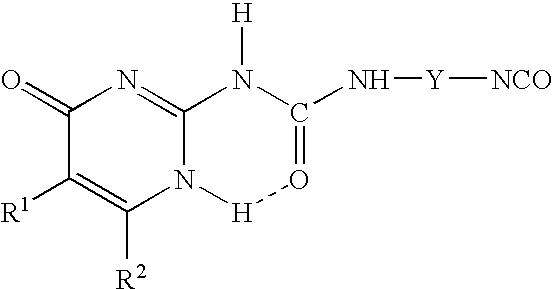
Multi-layer, positive working, thermally sensitive imageable elements, useful as lithographic printing plate precursors, are disclosed. The elements comprises a substrate, an underlayer over the substrate, and a top layer over the underlayer. The top layer comprises polymeric material, which is a solvent soluble novolac resin or a derivative thereof. The polymeric material is a (a) novolac that has a weight average molecular weight of at least 10,000, a derivative thereof functionalized with polar groups, or a derivative thereof functionalized with quadruple hydrogen bonding entities; (b) a solvent soluble m-cresol / p-cresol novolac resins that comprises at least 10 mol % p-cresol and has a weight average molecular weight of at least 8,000, a derivative thereof functionalized with polar groups, or a derivative thereof functionalized with quadruple hydrogen bonding entities; or (c) a mixture thereof. The imageable elements have increased scuff resistance and are thus less susceptible to damage during handling.

Description

FIELD OF THE INVENTIONThis invention relates to lithographic printing. More particularly, this invention relates to positive working, multi-layer thermally imageable elements in which the top layer comprises a novolac resin.BACKGROUND OF THE INVENTIONIn lithographic printing, ink receptive regions, known as image areas, are generated on a hydrophilic surface. When the surface is moistened with water and ink is applied, the hydrophilic regions retain the water and repel the ink, and the ink receptive regions accept the ink and repel the water. The ink is transferred to the surface of a material upon which the image is to be reproduced. Typically, the ink is first transferred to an intermediate blanket, which in turn transfers the ink to the surface of the material upon which the image is to be reproduced.Imageable elements useful as lithographic printing plates, also called printing plate precursors, typically comprise a top layer applied over the surface of a hydrophilic substrate. ...

Claims


Application Information

Patent Timeline
IPC IPC(8): B41C1/10G03F7/26G03F7/30G03C1/52G03F7/016G03F7/021G03F7/004
CPCB41C1/1016G03C1/49863B41C2210/02B41C2210/06B41C2210/24B41C2210/262B41C2210/22B41C2210/14
Inventor KITSON, ANTHONY P.RAY, KEVIN B.SHERIFF, EUGENE L.
Owner KODAK POLYCHROME GRAPHICS
Learn More