Double-data rate phase-locked-loop with phase aligners to reduce clock skew

a phase-locked loop and double-data-rate technology, applied in the field of phase-locked loops, can solve the problems of inherently limited speed, difficult to design analog circuits at a supply voltage as low as 1v using conventional approaches, and limited performance of integrated circuits

Inactive Publication Date: 2005-02-22
DIODES INC
View PDF18 Cites 25 Cited by
  • Summary
  • Abstract
  • Description
  • Claims
  • Application Information

AI Technical Summary

Problems solved by technology

Integrated circuit (IC) performance is often limited by clock generation and distribution.
However, it is quite challenging to design analog circuits at a supply voltage as low as 1V using conven

Method used


Image

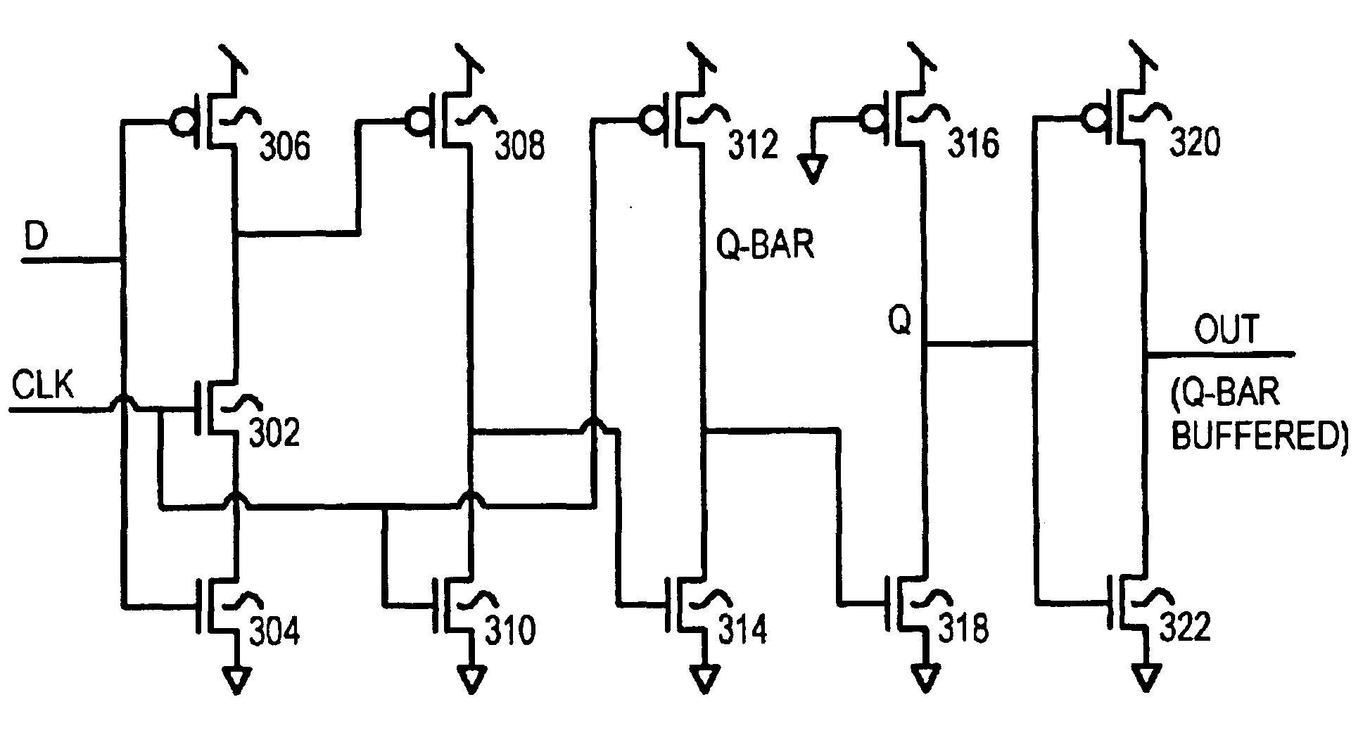
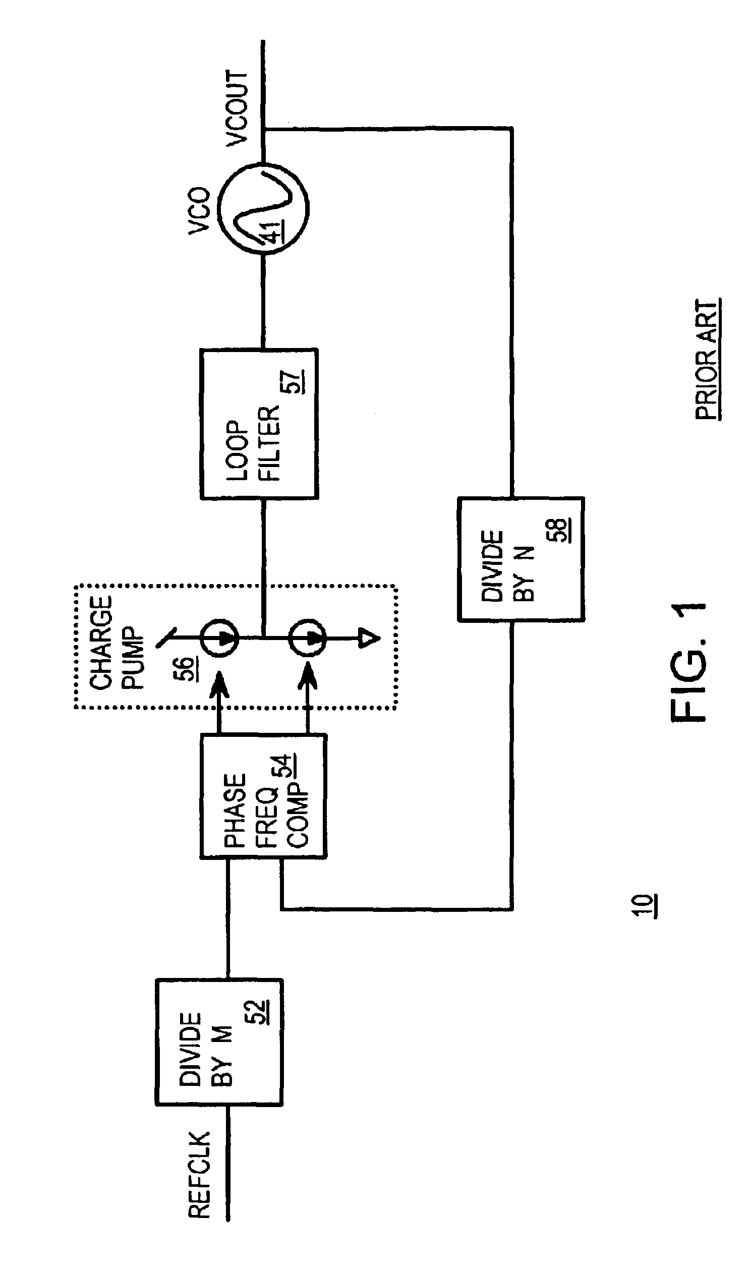
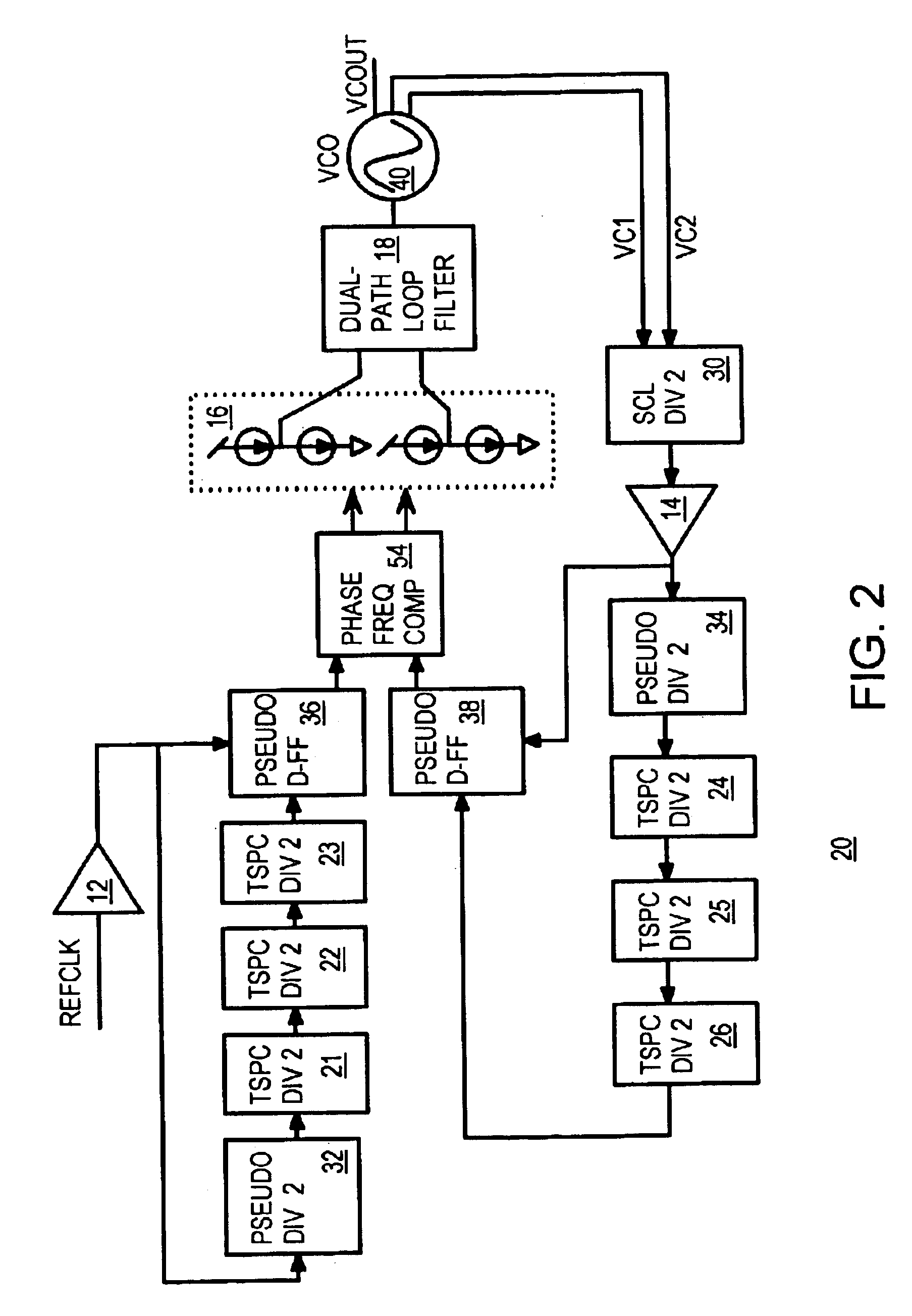
  • Double-data rate phase-locked-loop with phase aligners to reduce clock skew
  • Double-data rate phase-locked-loop with phase aligners to reduce clock skew
  • Double-data rate phase-locked-loop with phase aligners to reduce clock skew

Examples


Embodiment Construction

The present invention relates to an improvement in phase-locked loops (PLL's). The following description is presented to enable one of ordinary skill in the art to make and use the invention as provided in the context of a particular application and its requirements. Various modifications to the preferred embodiment will be apparent to those with skill in the art, and the general principles defined herein may be applied to other embodiments. Therefore, the present invention is not intended to be limited to the particular embodiments shown and described, but is to be accorded the widest scope consistent with the principles and novel features herein disclosed.

The inventors have realized that some clock generators have an output frequency that is a multiple of the input frequency, such as when the output is double the input frequency. The inventors further realized that both analog phase alignment and frequency dividing and digital phase alignment and frequency dividing can be used for...


PUM


Abstract

A phase-locked loop (PLL) has an analog divider in the feedback path that receives either the in-phase or quadrature-phase pair of outputs from a voltage-controlled oscillator (VCO) while the other pair, 90-degree out-of-phase, of outputs from the VCO is used for the PLL output. Phases between the PLL's input and output are inherently aligned. The analog output of the analog divider is converted to a digital clock signal and applied to a cascade of digital dividers to generate a reduced feedback clock. The reduced feedback clock is applied to the D input and the digital clock signal is applied to the clock input of a pseudo D-flip-flop that drives the feedback input of a phase-frequency detector that drives the charge pump to the VCO input. Another cascade of digital dividers and pseudo D-flip-flop re-align the reference clock input to the phase-frequency detector. Analog and digital re-alignment circuits reduce internal skew.

Description

BACKGROUND OF INVENTIONThis invention relates to phase-locked loops (PLL's), and more particularly to phase pre-alignment of clocks to the phase detector of the PLL.Integrated circuit (IC) performance is often limited by clock generation and distribution. High-frequency synchronous systems are sensitive to clock skew. Clock skew is the phase difference between an input clock and an output clock. Clock skew should be minimized to prevent race conditions, to shorten setup time and hold time requirements, and to increase the maximum possible operating speed.CMOS technology scaling has produced a requirement for low supply voltages to maintain device reliability with the smaller, more easily damaged devices. Employing a low supply voltage minimizes power consumption in digital circuits and extends battery life. However, it is quite challenging to design analog circuits at a supply voltage as low as 1V using conventional approaches, especially for high frequency clock generation.Currentl...

Claims


Application Information

Patent Timeline
IPC IPC(8): H03B5/08H03B5/12H03L7/099H03L7/183
CPCH03L7/099H03L7/183H03B5/1215H03B5/1228H03B2200/0078
Inventor LEUNG, GERRY C. T.LUONG, HOWARD C.
Owner DIODES INC
Why Eureka
Try Eureka