Methods and apparatus for positioning permanent magnetic blocks

a permanent magnetic block and magnetic technology, applied in the field of magnetic resonance image (mri) imaging, can solve the problems of difficult to position the permanent magnetic blocks on the yoke plate for an mri system with high uniformity and accuracy, and the assembled magnetic blocks are not at the perfect location as intended, so as to reduce the mechanical force

Inactive Publication Date: 2005-02-22
GE MEDICAL SYST GLOBAL TECH CO LLC
View PDF14 Cites 8 Cited by
  • Summary
  • Abstract
  • Description
  • Claims
  • Application Information

AI Technical Summary

Benefits of technology

In one aspect, a method for positioning permanent magnetic blocks is provided. The method includes providing a plurality of magnetized blocks, positioning the magnetized blocks on a yoke in a row by applying a mechanical force at a first end of the row with a first clamping member and at a second end of the row with a second clamping member, and repositioning the blocks by reducing the mechanical force at the first end by moving the first clamping member away from the first end, and moving the second clamping member toward the second end.

Problems solved by technology

However, it is difficult to place un-magnetized material blocks on a yoke plate first and then magnetize each block.
However, it is difficult to position the permanent magnetic blocks on the yoke for an MRI system with high uniformity and accuracy due to the nature of a very large magnetic force acting upon blocks from other blocks and with other magnetic objects (such as the pole piece).
Due to the nature of multiple factors, such as material physical tolerance, magnetic interaction force, assembly tolerance, process variation, etc., the assembled magnetic blocks will not be at a perfect location as intended.

Method used


Image

  • Methods and apparatus for positioning permanent magnetic blocks
  • Methods and apparatus for positioning permanent magnetic blocks
  • Methods and apparatus for positioning permanent magnetic blocks

Examples


Embodiment Construction

As used herein, an element or step recited in the singular and proceeded with the word “a” or “an” should be understood as not excluding plural said elements or steps, unless such exclusion is explicitly recited. Furthermore, references to “one embodiment” of the present invention are not intended to be interpreted as excluding the existence of additional embodiments that also incorporate the recited features.

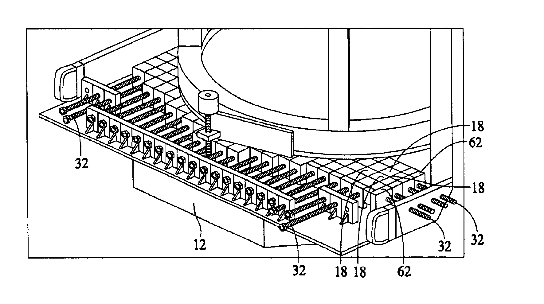
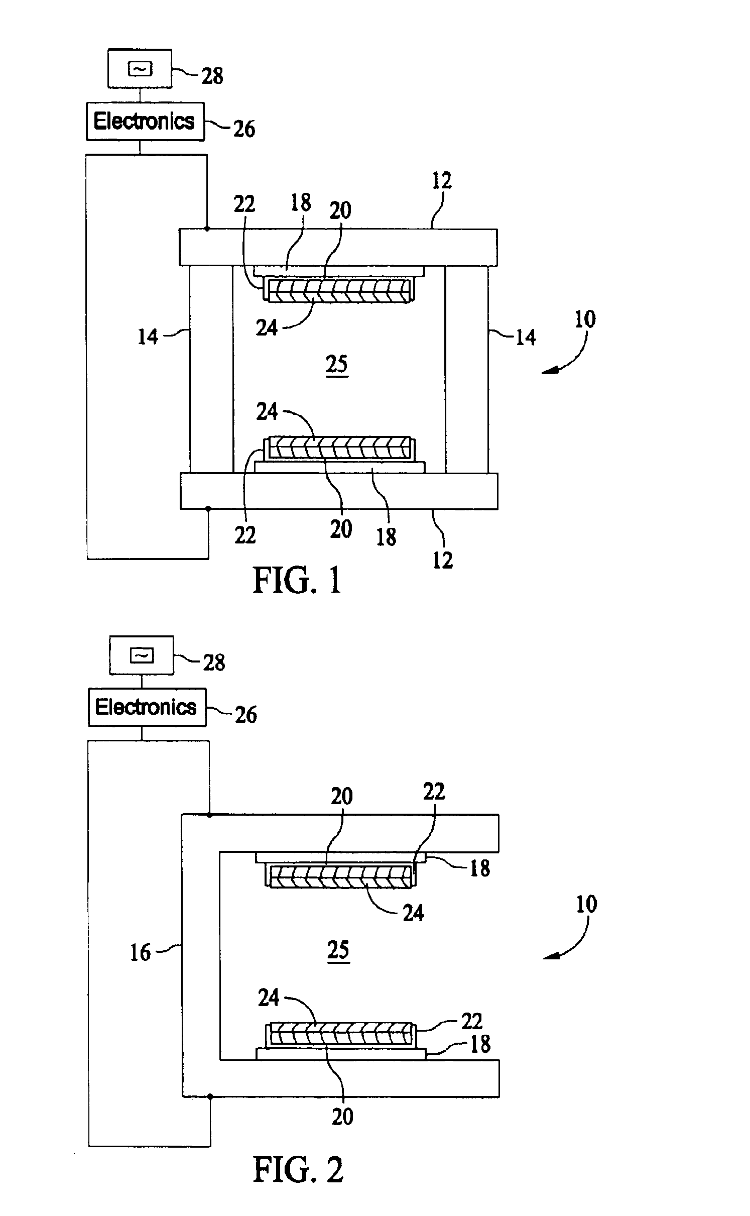
FIG. 1 is a block schematic diagram of an imaging system 10 such as an MRI system 10 including two plate yokes 12 and a plurality of columnar yokes 14 extending between plate yokes 12. Alternatively, an MRI system 10 with a single C shaped yoke 16 may be used as shown in FIG. 2. System 10 includes magnets 18 secured to yoke surfaces, pole piece bases 20 and support rings 22 secured to magnets 18 and a pole piece 24 is secured to each pole piece base 20 and support ring 22. A gap 25 is formed between pole pieces 24. A body part to be imaged is inserted into gap 25. MRI system 10...


PUM

PropertyMeasurementUnit
permanent magneticaaaaaaaaaa
mechanical forceaaaaaaaaaa
magneticaaaaaaaaaa

Abstract

A method for positioning permanent magnetic blocks includes providing a plurality of magnetized blocks, positioning the magnetized blocks on a yoke in a row by applying a mechanical force at a first end of the row with a first clamping member and at a second end of the row with a second clamping member, and repositioning the blocks by reducing the mechanical force at the first end by moving the first clamping member away from the first end, and moving the second clamping member toward the second end.

Description

BACKGROUND OF THE INVENTIONThis invention relates to magnetic resonance image (MRI) imaging, and, more particularly, to methods and apparatus for assembling magnetized permanent magnetic blocks used for an MRI magnetic field generator.A highly uniform magnetic field is useful in magnetic resonance imaging (MRI) and nuclear magnetic resonance (NMR) systems as a medical device or a chemical / biological device. Popular and low maintenance cost MRI systems currently available use a permanent magnet system that creates a middle range uniform field (0.2 to 0.5 Tesla) in a pre-determined space (imaging volume). A permanent magnet system usually uses multiple permanent magnet blocks such as NdFeB to form a single magnetic object and to achieve a desired highly uniform magnetic field in the imaging volume.For a magnetic field generator for an MRI that uses permanent magnets, the magnets used in such an apparatus are often formulated from a plurality of magnetized blocks. However, it is diffic...

Claims


Application Information

Patent Timeline
Patent Type & Authority Patents(United States)
IPC IPC(8): G01R33/38G01R33/383H01F7/02A61B5/055
CPCG01R33/383H01F7/0278Y10T29/49014
Inventor ZHENG, JINSHENGHUANG, JINHUALOCHNER, RONALD FLOYDSHEN, WEIJUNUNO, HIDEAKIWARD, GEERXU, BU-XIN
Owner GE MEDICAL SYST GLOBAL TECH CO LLC
Why Eureka
Try Eureka