
Dual-band omnidirectional antenna for wireless local area network

a wireless local area network and omnidirectional antenna technology, applied in the direction of individual energised antenna arrays, resonant antennas, radiating element structural forms, etc., can solve the problems of increased installation costs, increased installation costs, and increased installation costs, so as to achieve effective operation

Inactive Publication Date: 2005-02-22
SUNWOO COMM +1
View PDF13 Cites 134 Cited by
  • Summary
  • Abstract
  • Description
  • Claims
  • Application Information

AI Technical Summary

Benefits of technology

Accordingly, the present invent on has been made keeping in mind the above problems occurring in the prior art, and an object of the present invention is to provide a dual-band omnidirectional antenna, which has dual-band operating characteristics enabling the antenna to effectively operate in different frequency bands and omnidirectional radiation characteristics in each of the frequency bands.
Another object of the present invention is to provide a dual-band omnidirectional antenna, which can be miniaturized and manufactured at low cost and which is convenient to install.
The antenna has dual-band operating characteristics enabling the antenna to effectively operate in two different frequency bands and omnidirectional radiation characteristics in each of the frequency bands. Further, the antenna can be miniaturized to such an extent that it can be installed within a wireless communication device as well as outside it.

Problems solved by technology

Such a double-antenna structure is designed to enable the wireless communication device to be compatibly used in both the two WLAN systems, but it is very disadvantageous in structural and economic aspects.
While the ceramic patch antenna can be actually miniaturized, it is very expensive relative to a dipole antenna.
Further, the ceramic patch antenna requires special connector and cable, and the requirement for the special connector and cable is accompanied with a burden of additional installation costs.
Especially, since the patch antenna has directional radiation characteristics, it is not suitable for wireless LANs requiring omnidirectional radiation characteristics.

Method used


Image

  • Dual-band omnidirectional antenna for wireless local area network
  • Dual-band omnidirectional antenna for wireless local area network
  • Dual-band omnidirectional antenna for wireless local area network

Examples


Embodiment Construction

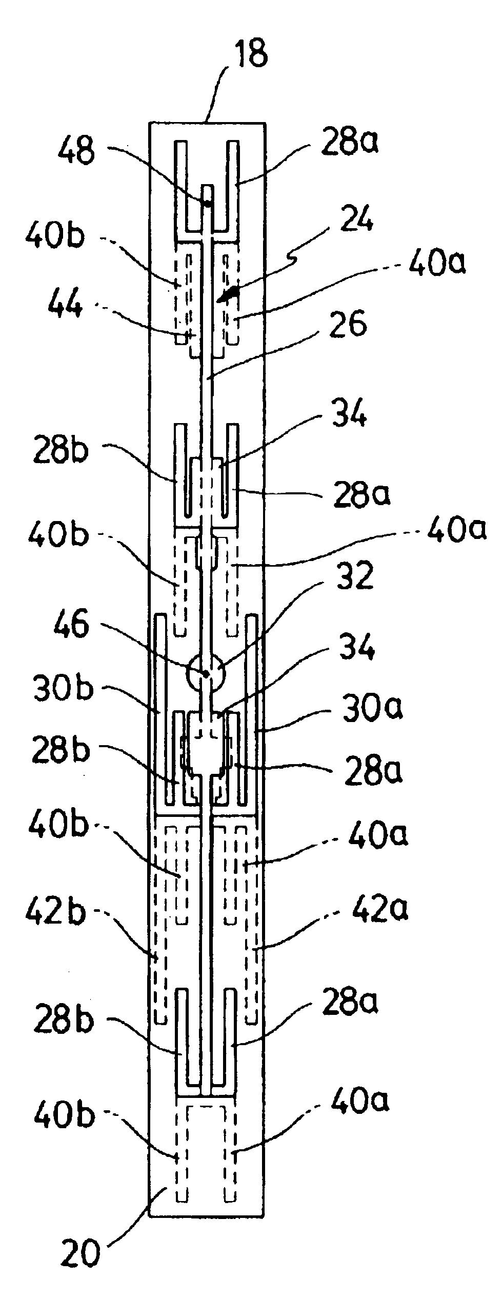
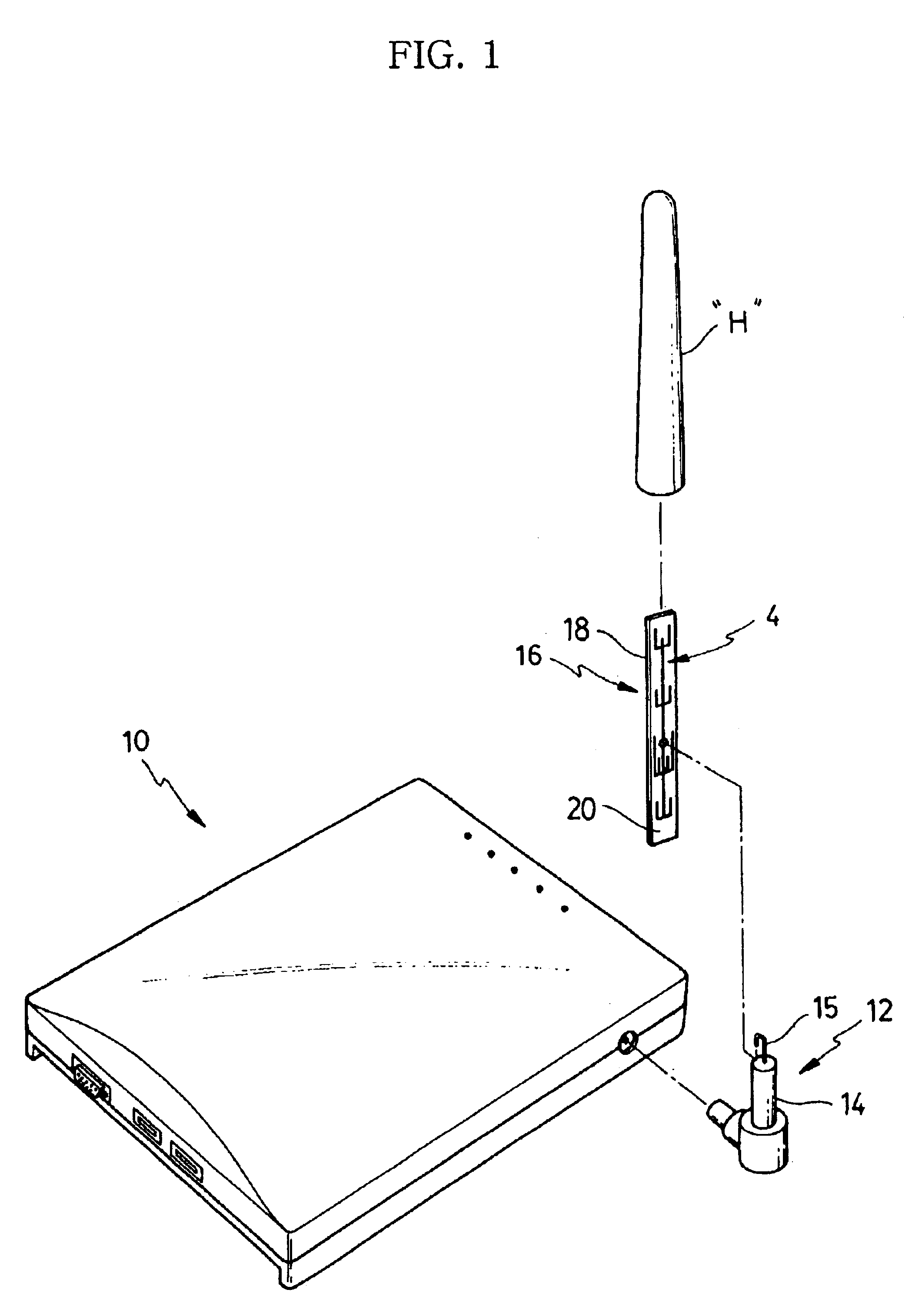
FIG. 1 shows a wireless communication device 10 using an antenna 16 according to the present invention. A wireless LAN system comprises a computer, a printer and other devices having LAN functions, as well as the wireless communication device 10. FIG. 1 illustrates that the antenna 16 is installed outside the wireless communication device 10 and is protected by a housing H. However, the antenna 16 is planar and can be miniaturized, so it can be installed within the wireless communication device 10.

The antenna 16 comprises a dielectric substrate 18 with front and rear surfaces on which conductive patterns 24 and 36 can be arranged, respectively. The dielectric substrate 18 has a relative dielectric constant of 1 to 10, preferably, 4.5, and has a predetermined Thickness, preferably, a value of 1.5 to 2.5 mm. The substrate 18 can be characterized in that it is planar and has a front surface 20 and a rear surface 22 which are actually parallel with each other and on which the conductive...


PUM


Abstract

The present invention relates to a dual-band omnidirectional antenna for wireless LANs. The antenna has a planar dielectric substrate, and first and second conductive patterns. The planar dielectric substrate has two parallel surfaces. The first conductive pattern is arranged on one surface of the substrate, and is provided with a first feeder line arranged on a longitudinal central line of the substrate and a plurality of radiating elements connected to the first feeder line and designed such that some of them operate in a high frequency band (4.9 to 5.85 GHz frequency band), and others thereof operate in a low frequency band (2.4 to 2.5 GHz frequency band). The second conductive pattern is arranged on the other surface of the substrate, and provided with a second feeder line arranged on a longitudinal central line of the substrate and a plurality of radiating elements connected to the second feeder line arid up-down symmetrically arranged with respect to the radiating elements on the first conductive pattern.

Description

BACKGROUND OF THE INVENTION1. Field of the InventionThe present invention relates generally to antennas used in wireless local area networks, and more particularly to a dual-band omnidirectional antenna, which has dual-band operating characteristics enabling the antenna to operate in two different frequency bands and omnidirectional radiation characteristics in each of the frequency bands.2. Description of the Prior ArtGenerally, Wireless Local Area Networks (WLANs) are used to transmit and receive digitally formatted data in a wireless manner between areas in a building, between different buildings, or between a building and an external area using wireless communication devices. In WLAN systems, antennas which operate in corresponding frequency bands are required for wireless communication devices.Meanwhile, WLAN systems are classified into an Institute of Electrical and Electronics Engineers (IEEE) 802.11b system in which a representative operating frequency is 2.4 GHz and an IEEE...

Claims


Application Information

Patent Timeline
IPC IPC(8): H01Q1/38H01Q5/00H01Q5/02H01Q9/04H01Q9/28H01Q1/24H01Q1/42H01Q9/18H01Q1/22H01Q5/10H01Q5/15H01Q5/371H01Q9/06H01Q21/08
CPCH01Q1/22H01Q1/2258H01Q1/24H01Q5/371H01Q9/065H01Q21/08H01Q1/38
Inventor CHOI, JONG-IN
Owner SUNWOO COMM
Learn More