

Target analyte sensors utilizing microspheres
a technology of analyte sensors and microspheres, which is applied in the direction of fluorescence/phosphorescence, nucleotide libraries, enzymology, etc., can solve the problems of tens of functionalities being applied, slow process, and difficulty in applying the various chemistries associated with chemical functionalities at the sensor's end
- Summary
- Abstract
- Description
- Claims
- Application Information
AI Technical Summary
Problems solved by technology
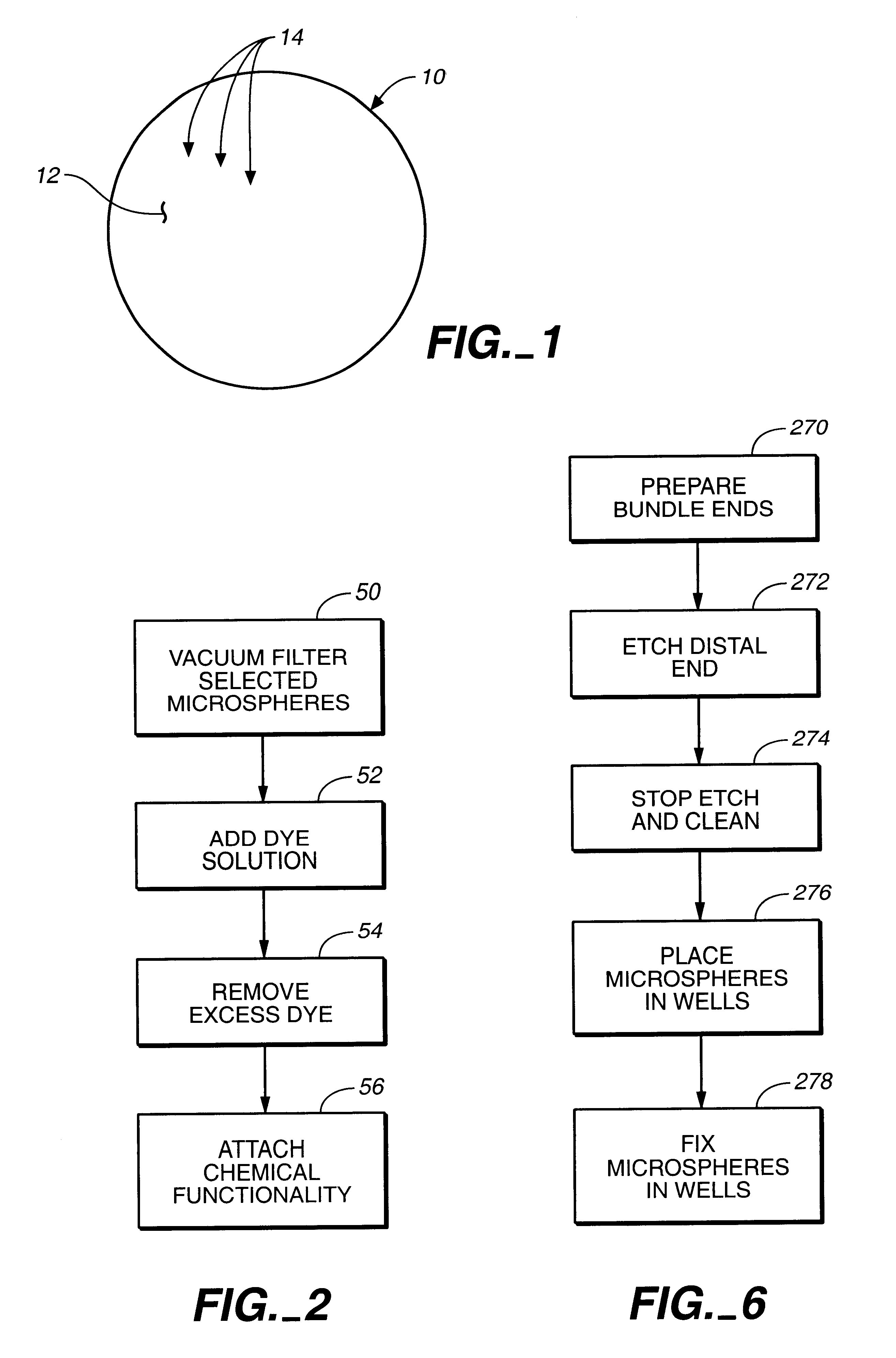
Method used
Image

Examples
example 1
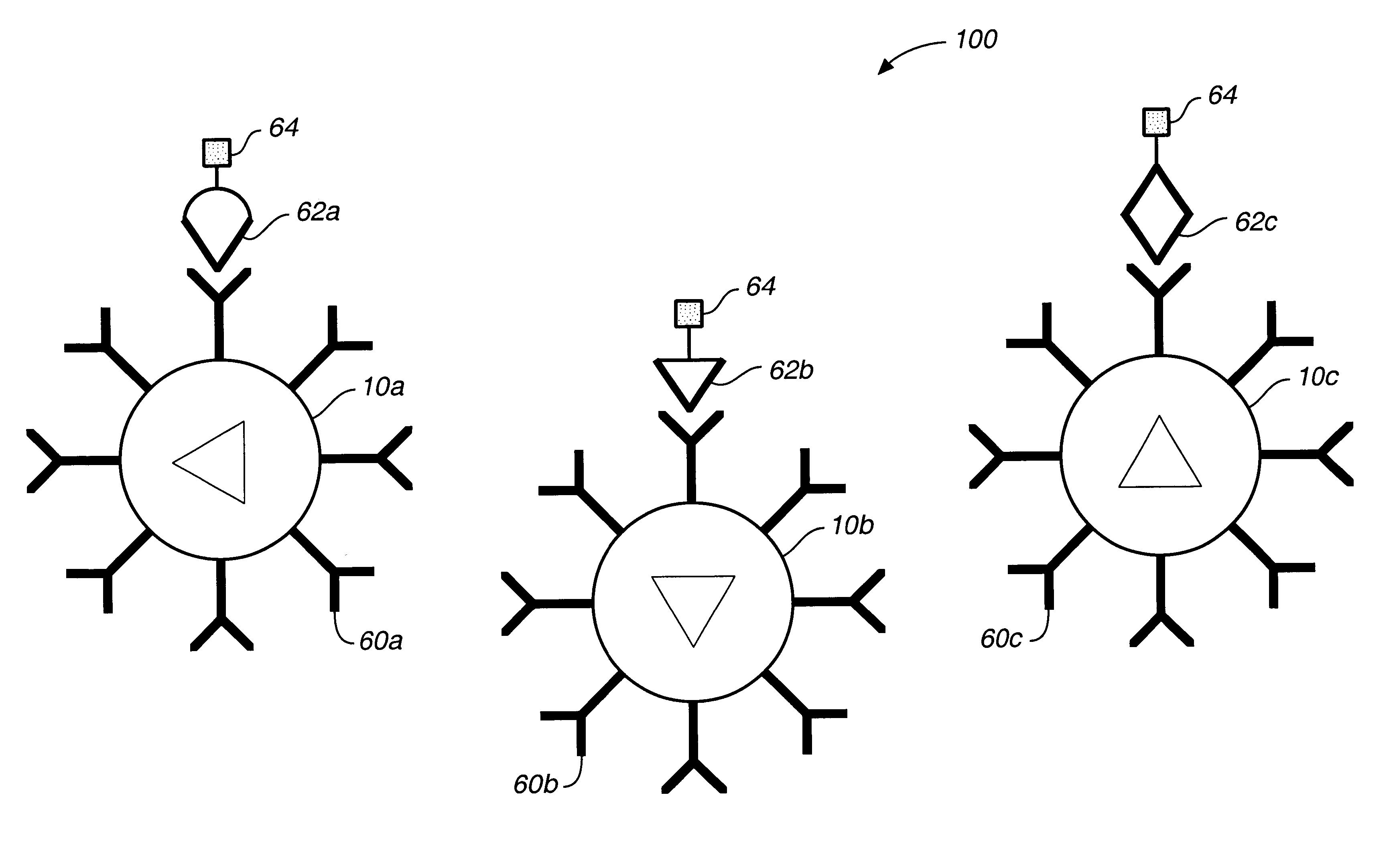
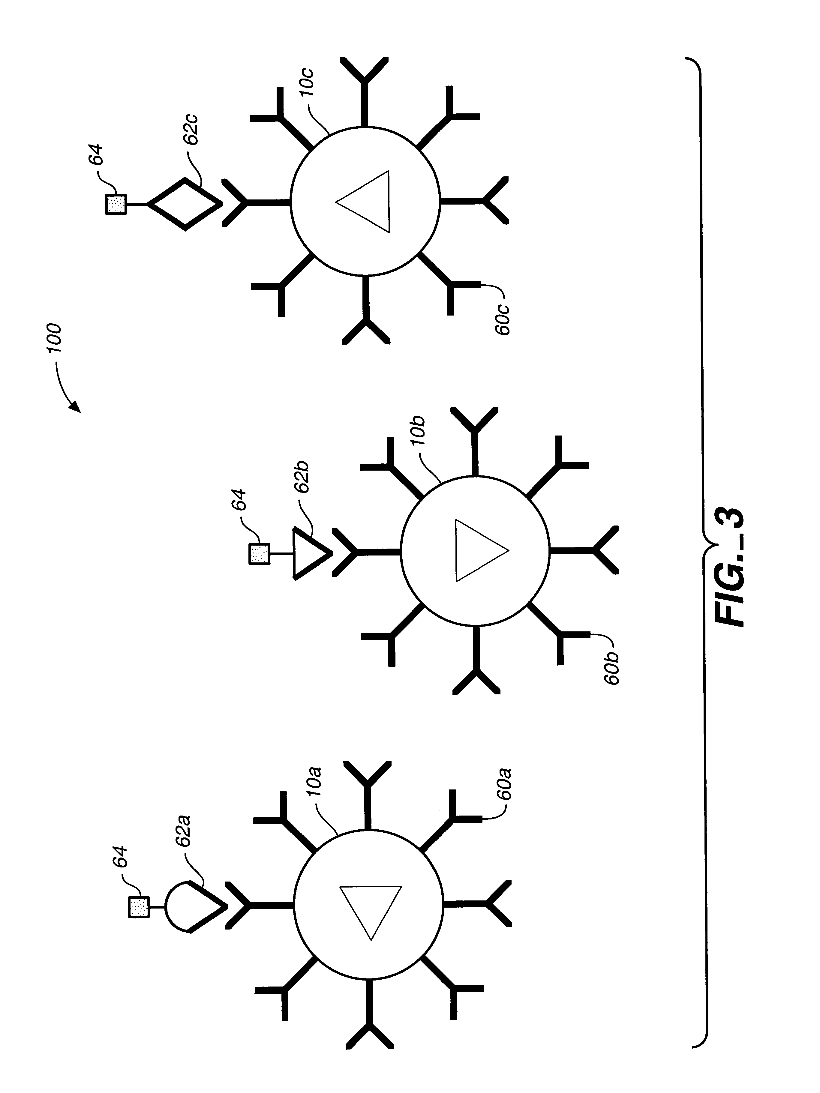
sed Sensor
Subpopulation A
Bioactive agent: Alkaline phosphataseTarget substrate: fluorescein diphosphate (FDP)Reported dye ratio: 1:1 ratio of DiIC:TRC, where DiIC is 1,1′,3,3,3′,3′-hexamethyl-indodicarbocyanine iodide and TRC is Texas Red cadaverine
A range of ratios of light intensities are selected that are representative of the optical signature for the dye ratio of the subpopulation based on the quantum yield of the two dyes. The optical signature for this subpopulation is: iIC λ intensity-ave. DiIC backgroundTRC λ intensity-ave·TRC background=0.847±0.23
Subpopulation BBioactive agent: B-Galactosidase;Target substrate=fluorescein di-B-galactopyranoside (FDG)Reporter dye ratio: 10:1 ratio of DiIC:TRC which translates to an optical signature of: DiIC λ intensity-ave. DiIC backgroundTRC λ intensity-ave. TRC background=4.456±1.27
Subpopulation CBioactive agent: B-glucuronidaseTarget substrate=fluorescein di-B-D-glucuronide (FDGicu).Reporter dye ratio: 1:10 r...
PUM
| Property | Measurement | Unit |
|---|---|---|
| sizes | aaaaa | aaaaa |
| sizes | aaaaa | aaaaa |
| sizes | aaaaa | aaaaa |
Abstract
Description
Claims
Application Information