Structured system for monitoring and controlling the engineering equipment of an installation

Inactive Publication Date: 2005-02-22
ECOPROG
View PDF13 Cites 20 Cited by
  • Summary
  • Abstract
  • Description
  • Claims
  • Application Information

AI Technical Summary

Benefits of technology

Thus, connection of the controllers to the input-output device of the central computer module in a hierarchical star circuit makes it possible, even with the use of cable sections of a limited length, to ensure a constancy of signal parameters during the transmission thereof over these sections while preserving the scheme

Problems solved by technology

Many engineering systems are even totally devoid of any means of monitoring—centralized supervision, measurement and control.
Analysis of existing systems indicates that to a greater or lesser degree such solutions have the following drawbacks in common: shortage of information for the maintenance services; lack of coordination between monitoring elements of various engineering systems; poor overall reliability of technological processes; use of morally outdated hardware; lack of unification of the equipment and cabling; lack of readily available spare equipment; high operational costs; slow reaction to failures of the equipment and restoration of the serviceability thereof; absence of engineering solutions to ensure sustained functioning of the system; lack of automatic control functionality; limited dispatch capabilities due to the absence of means for remote transmission of information to the maintenance services of the building.
In buildings with a well-developed infrastructure, complex and expensive engineering and utility syste

Method used


Image

  • Structured system for monitoring and controlling the engineering equipment of an installation
  • Structured system for monitoring and controlling the engineering equipment of an installation

Examples


Embodiment Construction

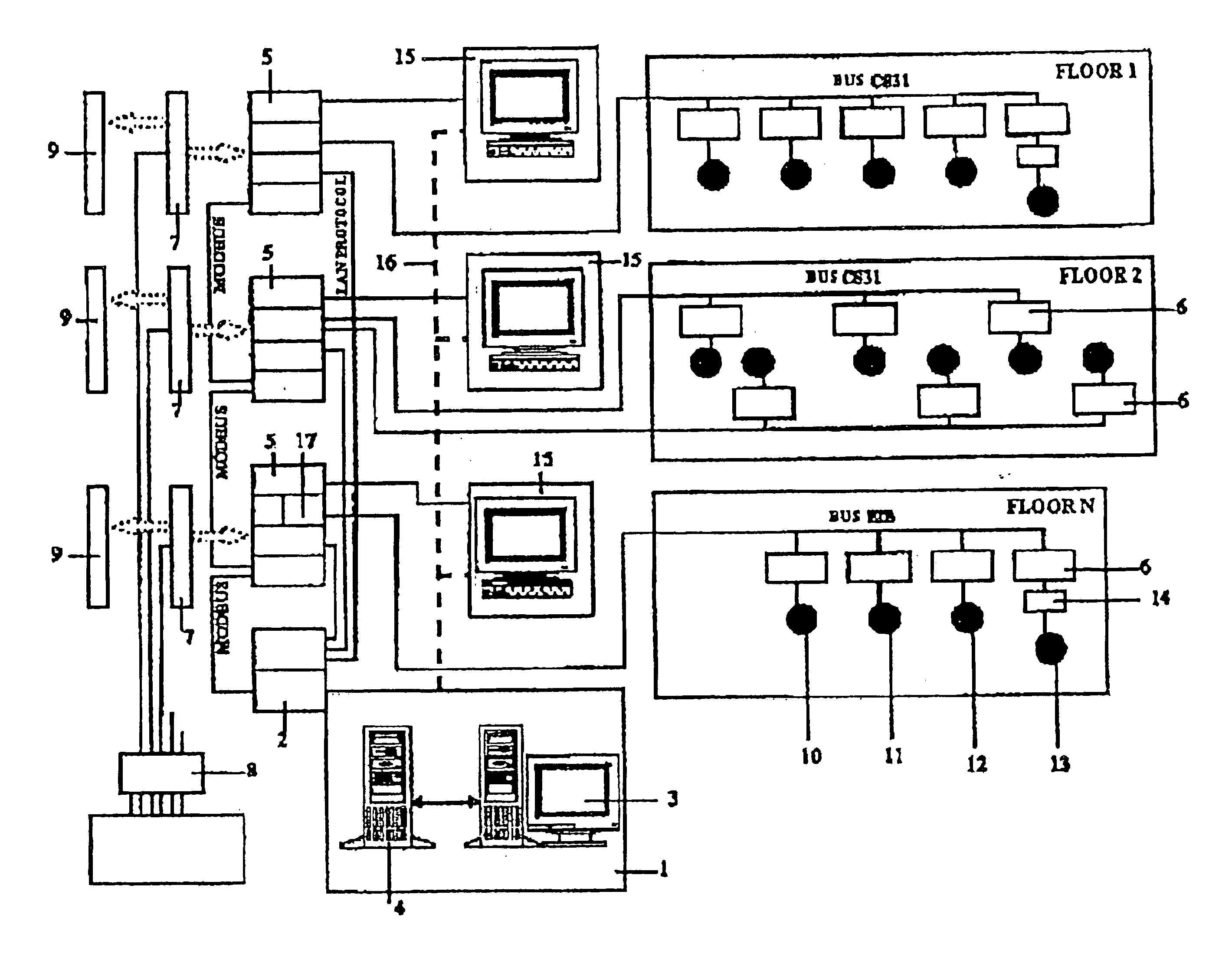
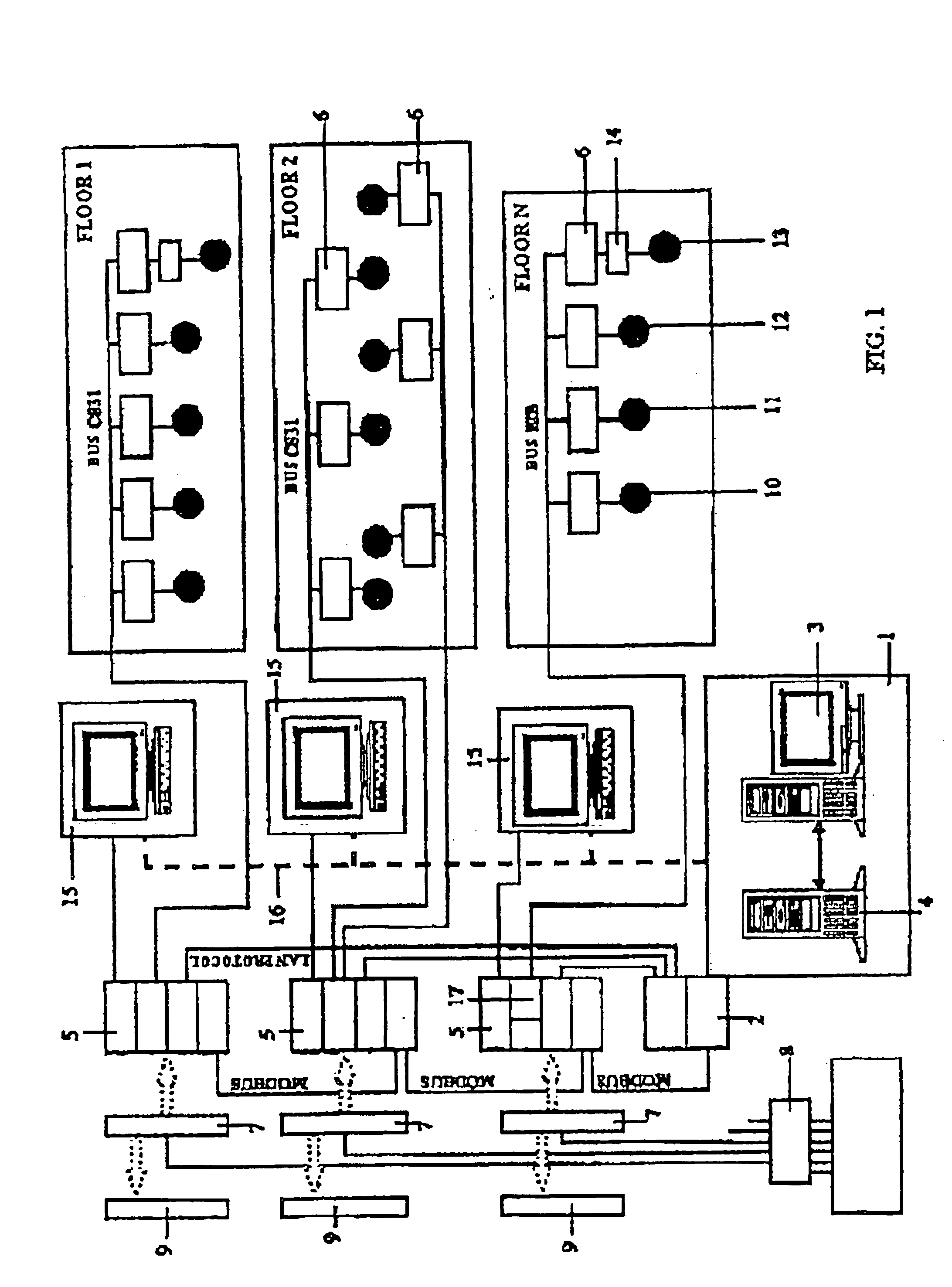
The present invention will be described in terms of a specific embodiment which, while not being the only possible embodiment, visually demonstrates the feasibility of achieving the requisite engineering result.

The structured system for monitoring and controlling the engineering equipment of an installation in the form of a building comprising several floors (FIG. 1) includes a central computer module 1 with an input-output device 2. The module is a programmable computer server station 3 having functions, according to the software, that provide for the centralized acquisition of monitoring data through information channels within a single network protocol, as well as for the processing of said data and for the output of control signals to the control devices of the units and apparatus of the engineering equipment in the building. The server station also includes a redundant server 4.

Used in the capacity of the programmable computer server station can be the station described in DE, ...


PUM


Abstract

The present inventions pertains to the field of automatic control systems based on computer technology, and essentially relates to a structured system for monitoring and controlling the engineering equipment in an installation, mainly a building comprising several floors. The system includes a central computer module with an input-output device as well as a plurality of monitoring and/or measuring and/or control sensors and/or control devices for the units and apparatus of the engineering equipment in the building. The module consists of a programmable computer server station having functions, according to the software, that provide for the centralized reception of monitoring data through information channels within a single network protocol, as well as for the processing of said data and for the output of control signals towards the control devices for the units and apparatus of the engineering equipment in the building. This system further includes controllers connected in a “star” circuit to the input-output device of the central computer module. Each controller has a plurality of remote input-output modules connected serially thereto, while each of said modules has a corresponding sensor or a control device connected thereto. At least one additional computer station is connected through its input-output module to the corresponding controller that ensures, according to the software, the local monitoring and the control of the units and apparatus in at least one functionally independent section of the engineering equipment in the building.

Description

This application claims priority of Russian Application No. 98117308 filed Sep. 21, 1998 and international Application No. PCT / RU99 / 00342 filed Sep. 20, 1999, the complete disclosure of which is hereby incorporated by reference.FIELD OF THE INVENTIONThe present invention relates to the art of automatic control systems based on computer technology and, more specifically, to the design of a system for monitoring and measuring the operational parameters of and controlling the life-support engineering equipment, mainly of an intellectual type, of a building.DESCRIPTION OF THE PRIOR ARTTraditional solutions presuppose automation of local engineering systems of an installation rather than taking an integrated approach to the automation of said installation as a whole. Presently, large installations are equipped with a plurality of different engineering systems to support the life of such installations and the technological processes of the organizations located therein. The number of such...

Claims


Application Information

Patent Timeline
IPC IPC(8): G05B19/04G05B19/042G05B15/02G05B23/02G05B15/00G05B23/00
CPCG05B15/02G05B19/0421G05B23/0213G05B2219/25232G05B2219/25016G05B2219/25022G05B2219/25035G05B2219/25011
Inventor GINZBURG, VITALIY VENIAMINOVICHBURMISTROV, VIKTOR ALEKSANDROVICHFABRICHNEV, ALEKSANDR VASILEVICHERSHOV, VLADIMIR VLADIMIROVICH
Owner ECOPROG
Why Eureka
Try Eureka