Method for manufacturing airtight vessel and image-forming apparatus using airtight vessel

Inactive Publication Date: 2005-03-01
CANON KK
View PDF27 Cites 6 Cited by
  • Summary
  • Abstract
  • Description
  • Claims
  • Application Information

AI Technical Summary

Benefits of technology

The object of the present invention is to provide a method for manufacturing an image-forming apparatus with a long life and prov

Problems solved by technology

However, there have been problems as described below for maintaining a vacuum with the foregoing getter.
Most of the gases discharged by sealing are trapped in the airtight vessel, again contaminating the room of the airtight vessel that has been once cleaned by the baking step.
However, such a construction makes evacuation time of the vessel too long or the diameter of the evacuation tube itself should be large owing to the ge

Method used


Image

  • Method for manufacturing airtight vessel and image-forming apparatus using airtight vessel
  • Method for manufacturing airtight vessel and image-forming apparatus using airtight vessel
  • Method for manufacturing airtight vessel and image-forming apparatus using airtight vessel

Examples


example 1

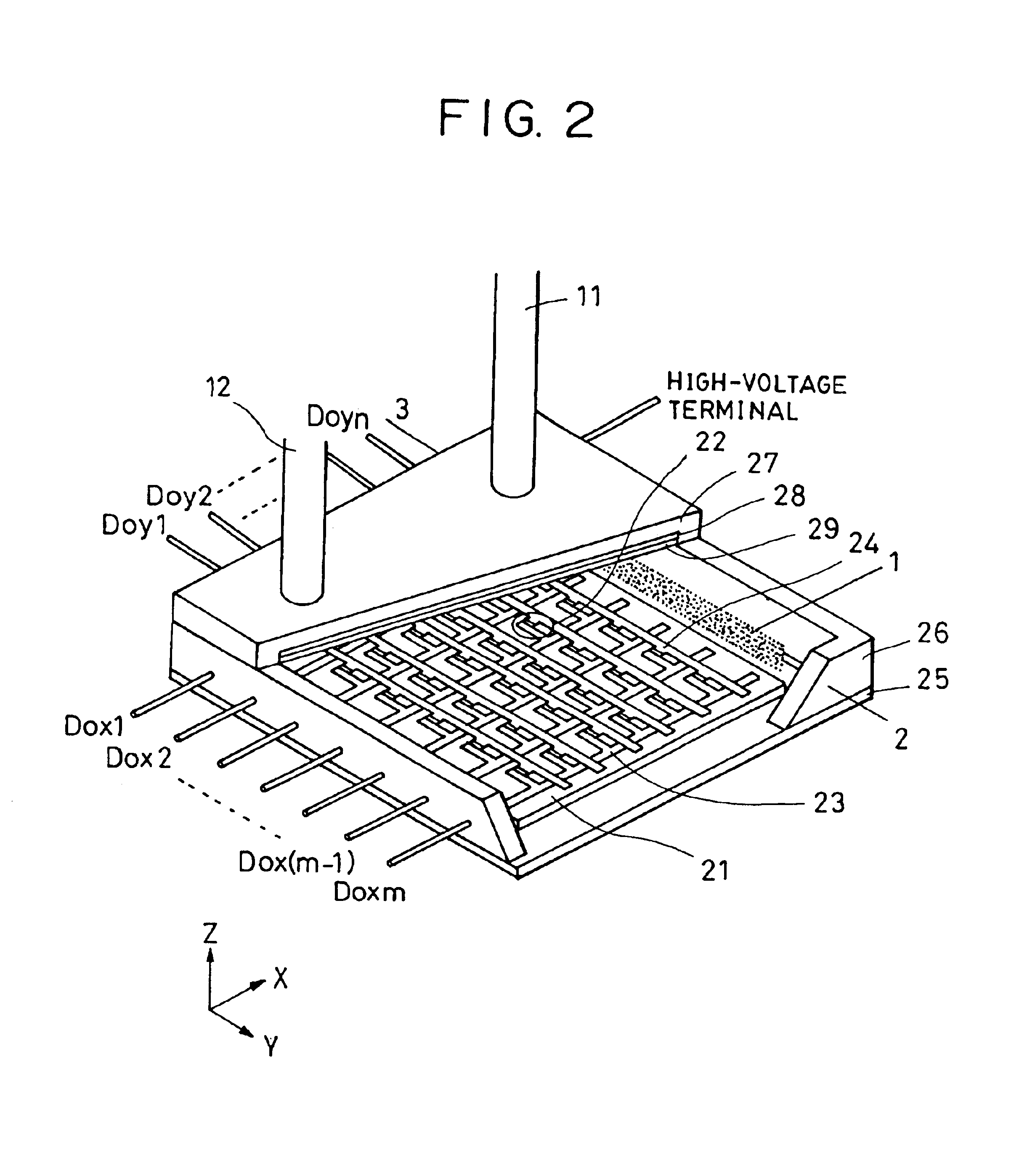
The image-forming apparatus having a construction as shown in FIG. 2 was manufactured. A plurality of surface conduction type electron emission elements—one kind of cold cathode electron emission elements—were formed on the rear plates in this example. fluorescent films were provided on the face plate and a color image-forming apparatus with an effective display area having a diagonal length of 15 inches and vertical to transverse length ratio of 3:4 was manufactured.

The image-forming apparatus according to this example will be described referring to FIG. 2.

FIG. 2 is a perspective view showing the outline of the image-forming apparatus used in this example, in which a part of the panel is cut off to show the internal structure.

The reference numerals 25, 26 and 27 in the drawing correspond to a rear plate, a supporting frame and a face plate, respectively, forming a vessel for maintaining vacuum in the display panel. A sealing bonding step is required in order to endow junction among...

example 2

This example also gives an image-forming apparatus using the surface conduction type electron emission element (refer to FIGS. 2, 3 and 4 with respect to the image-forming apparatus).

The method for manufacturing the image-forming apparatus according to this example will be described referring to FIG. 8.

(Manufacturing of Rear Plate)

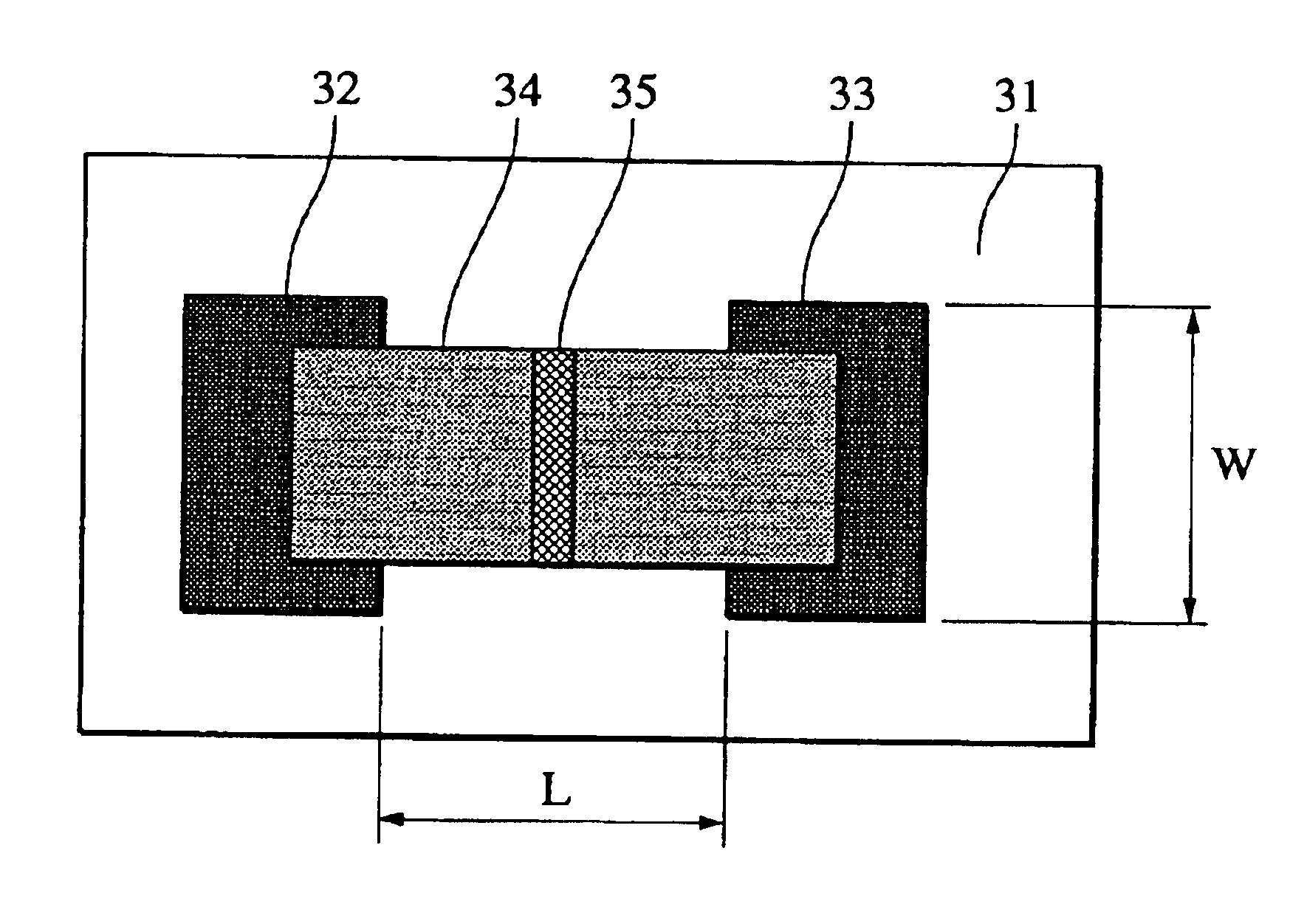
(R-1) After cleaning the soda lime glass, the lower wiring 23 was formed by screen-printing on the rear plate 25 on which a silicon oxide film was formed by sputtering. Then, an interlayer insulation film is formed between the lower wiring 23 and upper wiring 24. After forming the upper wiring 24, the element electrodes 32 and 33 that are connected to the lower wiring 23 and upper wiring 24 were formed.

(R-2) After depositing the conductive thin film 34 comprising PdO by sputtering, the film was patterned to a given shape.

(R-3) The frit glass for fixing the supporting frame 26 was formed at a given position.

The rear plate, on which the surface conduction ty...

example 3

An image-forming apparatus using the airtight vessel with the construction as shown in FIG. 10 was manufactured in this example.

A plurality of field emission elements were formed on the rear plate 111 and providing a spacer 116 between face plate 112 and rear plate 111 as a supporting member to be used under atmospheric pressure in order to make the image-forming apparatus lightweight. The face plate 112 is provided with fluorescent films and a color image-forming apparatus with a vertical to transverse length ratio of 3:4 whose effective display area has a diagonal length of 10 inches was manufactured.

The construction of the airtight vessel constituting the image-forming apparatus according to this example, then the method for manufacturing the same, will be described referring to FIG. 11. In FIG. 10, the reference numeral 111 denotes a rear plate, the reference numeral 112 denotes a face plate, the reference numeral 113 denotes a cathode, the reference numeral 114 denotes a gate e...


PUM


Abstract

A method for manufacturing an airtight vessel seals an evacuation tube after evacuating the inside of the vessel using the evacuation tube. A getter previously disposed in the vessel is activated followed by fusing a part of the evacuation tube to seal the vessel while heating the vessel.

Description

BACKGROUND OF THE INVENTION1. Field of the InventionThe present invention relates to a method for manufacturing an airtight vessel. The present invention especially relates to a method for evacuating gases discharged while sealing an evacuation tube in the method for manufacturing the airtight vessel to be used for an image-forming apparatus.2. Description of Related ArtElectron emission elements known in the art have been mainly categorized into a thermionic-cathode and a cold-cathode. The cold-cathode include a field emission type (referred to FE-type hereinafter), metal / insulation layer / metal type (referred to MIM-type hereinafter) and surface conduction type electron emission elements.Examples of the FE-type electron emission elements are disclosed by W. P. Dyke and W. W. Dolan in “Field Emission”, Advance in Electron Physics, 8, 89 (1956) or by C. A. Spindt in “Physical Properties of Thin-film Field Emission Cathodes with Molybdenum Cones”, J. Appl. Phys., 47, 5248 (1976).Examp...

Claims


Application Information

Patent Timeline
IPC IPC(8): H01J9/40H01J9/38H01J9/00H01J9/385H01J9/39
CPCH01J9/40H01J9/38H01J1/30H01J9/24
Inventor FUJIMURA, HIDEHIKOARUGA, TORUOGURA, MASAAKI
Owner CANON KK
Why Eureka
Try Eureka