
Controlling method for manufacturing process

Inactive Publication Date: 2005-03-01
LAPIS SEMICON CO LTD
View PDF22 Cites 27 Cited by
  • Summary
  • Abstract
  • Description
  • Claims
  • Application Information

AI Technical Summary

Benefits of technology

It is an objective of the invention to provide a controlling method for a manufacturing process so as to effectively control the operating condition of the manufacturing process.
According to the present invention, the operating condition of the manufacturing process can effectively be controlled with a high degree of accuracy.

Problems solved by technology

However, in the conventional method for controlling a manufacturing process, since there are too many graphs and reports needing to be controlled, it is very difficult to make a judgement about timing of carrying-in, timing of carrying-out, and a throughput of product.
And, it requires many man-hours to make a judgement about them.
More further, there are too many manufacturing parameters and they undergo a lot of changes in accordance with an operating condition of a manufacturing apparatus, and the judgement and instruction of the administrator.
Therefore, it is very difficult to logically define the impacts on productivity considering the factors mentioned above.
For example, when a plurality of manufacturing apparatus are stopped together, it is very difficult to exactly find out a productivity deterioration considering various factors (priority, urgency, and so on).

Method used


Image

  • Controlling method for manufacturing process
  • Controlling method for manufacturing process
  • Controlling method for manufacturing process

Examples


Embodiment Construction

Preferred embodiments of the present invention will hereinafter be described in detail with reference to the accompanying drawings. The drawings used for this description typically illustrate major characteristic parts in order that the present invention will be easily understood.

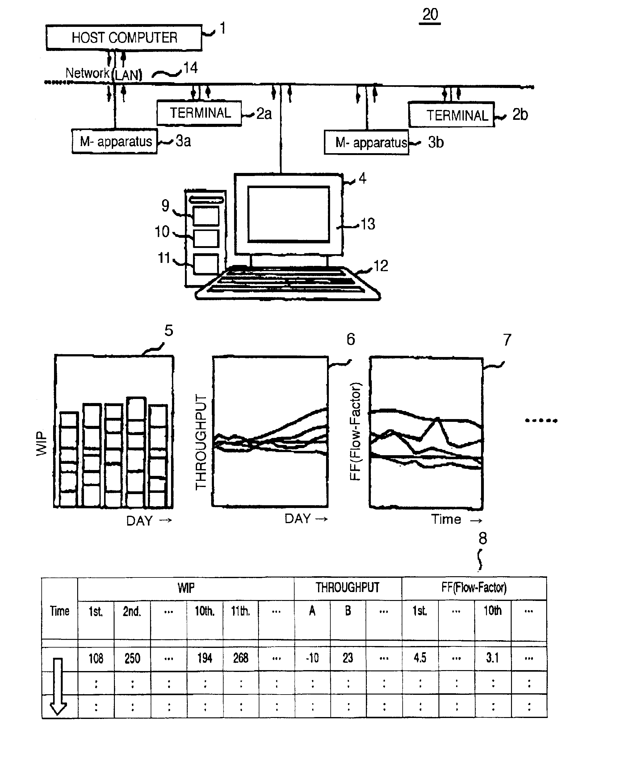
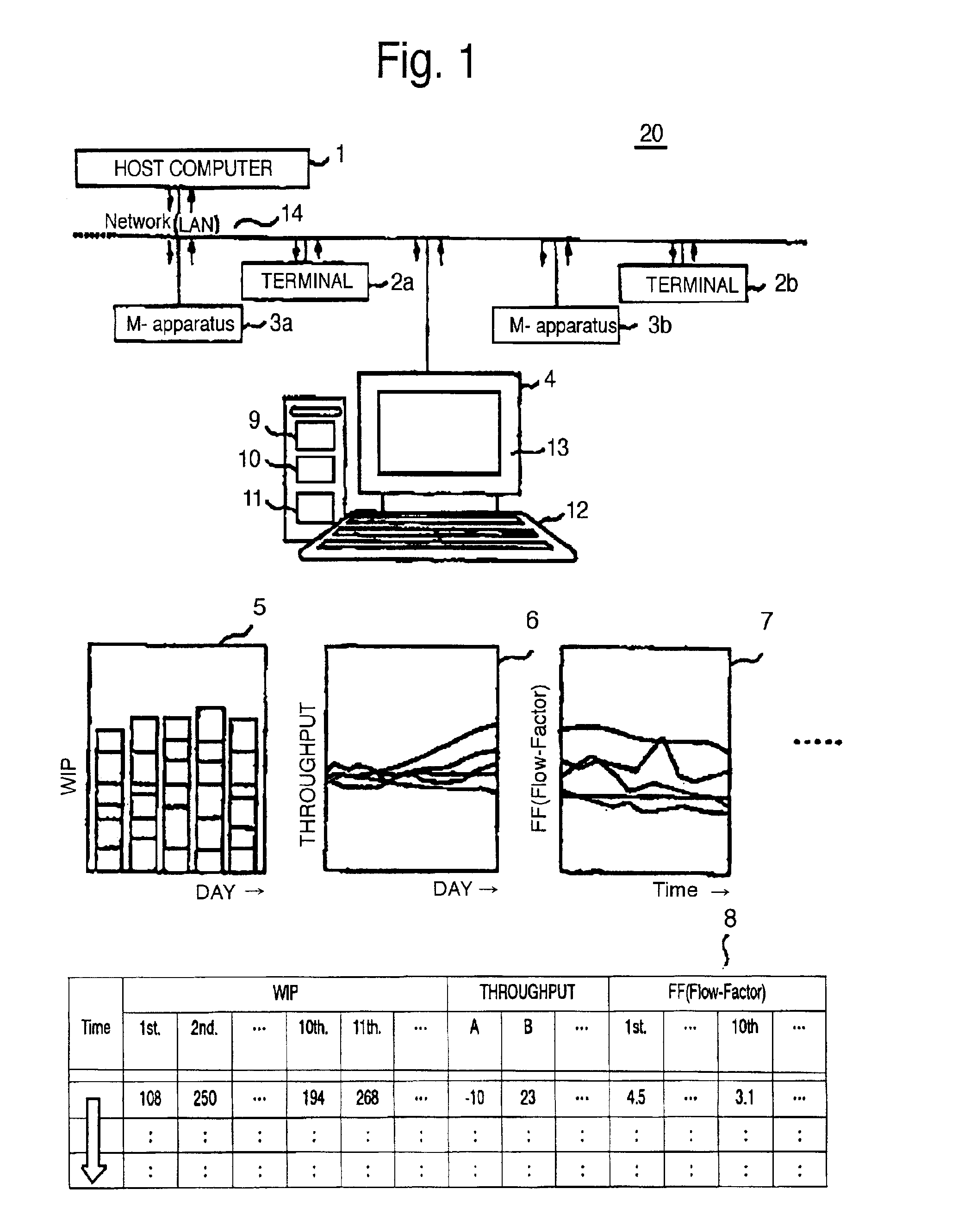
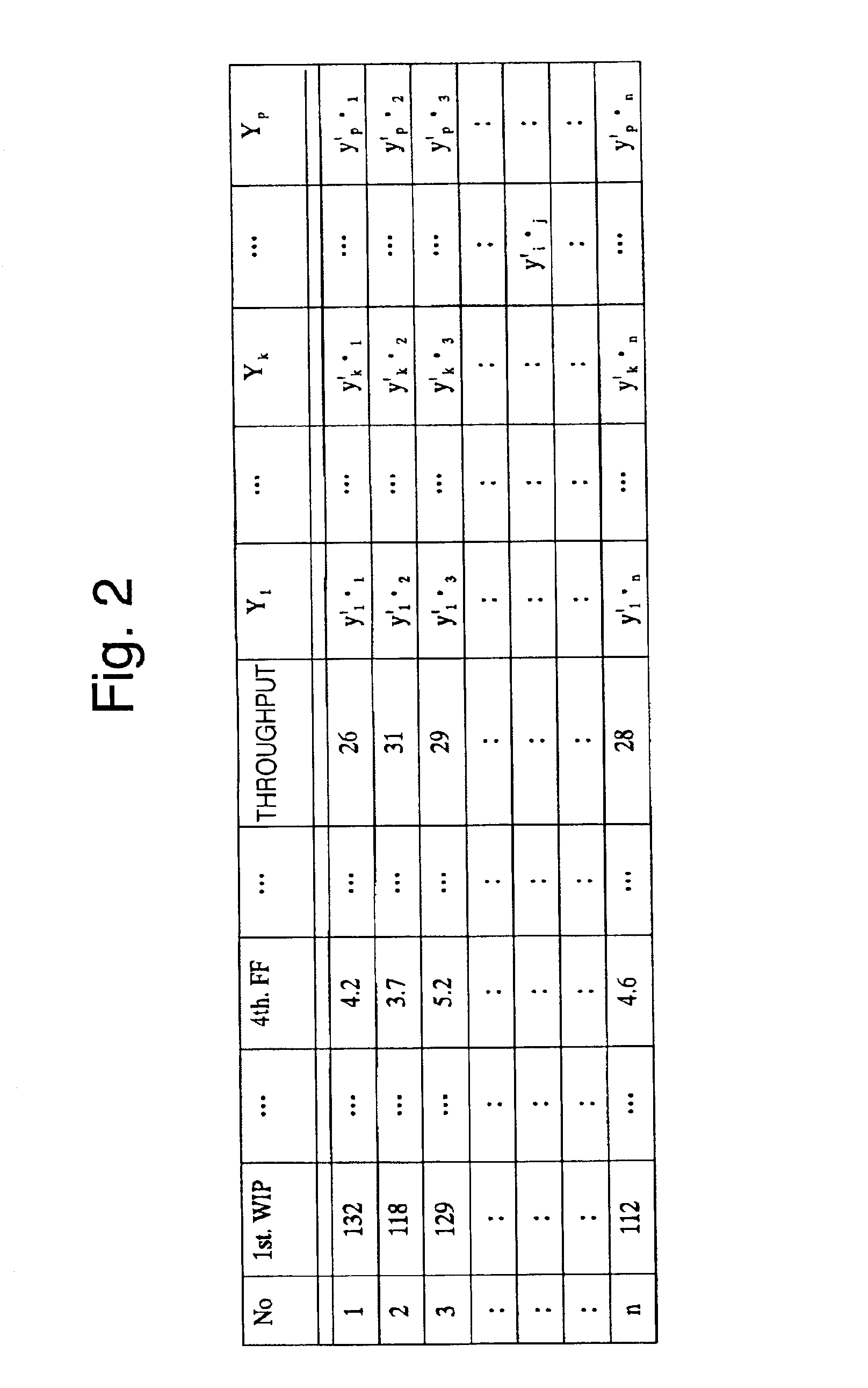
FIG. 1 is a block diagram showing a control system 20 according to a first preferred embodiment of the present invention. The control system 20 includes a host computer 1, a local area network (LAN) 14 and a fab-server 4 set in a fabricating laboratory. The host computer 1 performs as a data base (DB) storing various information. Such information is, for example work-in-progress (WIP) information and transport information which are inputted from plural terminals 2a and 2b, and apparatus information which is inputted from plural manufacturing apparatuses 3a and 3b. The fab-server 4 includes an arithmetic circuit 9, a memory 10, a comparator 11, and input and output devices 12 and 13. The control system 20 is...


PUM


Abstract

In a method of controlling a manufacturing process, a Mahalanobis space of plural manufacturing control parameters is generated on the basis of first sampled data. Then, a Mahalanobis distance from the Mahalanobis space and second sampled data is calculated. A manufacturing process is determined to be under a malfunction operating condition by comparing the Mahalanobis distance and a threshold value.

Description

BACKGROUND OF THE INVENTION1. Field of the InventionThe present invention relates to a method of managing a manufacturing process, and more particularly to a managing method for a semiconductor manufacturing process including a wafer process (WP), a test process (TP) and an assembly process (AP).The present application claims priority under 35 U.S.C. §119 to Japanese Patent Application No. 2001-122621, filed Apr. 20, 2001, which is herein incorporated by reference in its entirely for all purposes.2. Description of the Related ArtAs a conventional method for controlling a manufacturing process, an administrator, for example manager, assistant manager, or leader, controls various manufacturing parameters, judges conditions of the various manufacturing parameters, and then outputs instructions in accordance with the conditions. A controlling system is established such that a graph and a report in accordance with various process data are automatically outputted through a local area netw...

Claims


Application Information

Patent Timeline
IPC IPC(8): G06Q10/00G01M99/00G05B19/418G05B23/02G06Q10/10G06Q50/00G06Q50/04H01L21/02
CPCG05B19/41875G06Q10/10G05B2219/32221G05B2219/31477Y02P90/02
Inventor HAYASHI, SHUNJI
Owner LAPIS SEMICON CO LTD
Learn More