Light intensity simulation method, program product, and designing method of photomask

a technology of light intensity simulation and program product, applied in the field light intensity simulation program product, and photomask design method, can solve the problems of local flare, non-conventional establishment of light intensity simulation method taking into account local flare influence, and phenomenon called. achieve the effect of high accuracy

Inactive Publication Date: 2005-03-01
FUJITSU SEMICON LTD
View PDF7 Cites 35 Cited by
  • Summary
  • Abstract
  • Description
  • Claims
  • Application Information

AI Technical Summary

Benefits of technology

The present invention has been made in view of the above problems, and its object is to provide a light intensity simulation method, a light intensity simulation program product, a recording medium and a designing method of a photomask, which can secure high accuracy while taking local flare into consideration.
According to the present invention, it is possible to carry out the simulation while considering the influence of the local flare appropriately. Therefore, high accuracy can be secured. Further, when the photomask is corrected based on the result of such simulation, it is possible to design a desired photomask.

Problems solved by technology

In recent years, a phenomenon called local flare is becoming a problem as the exposure wavelength becomes shorter.
However, a light intensity simulation method taking the influence by the local flare into consideration has not been established conventionally.
For this reason, there is a problem that the light intensity simulation with high accuracy cannot be carried out.
Accordingly, it becomes difficult to design the photomask for transferring desired patterns onto a photosensitive material such as the photosensitive resist.
However, light whose optical path is different from the designed one is generated due to reflection and scattering of the surface and the inside of a lens of illumination optical system, mask, projection lens and the like, nonuniformity of a refractive index of lens material, and the like.
Due to a peculiarity of lens material corresponding to such a short wavelength, it is becoming a problem that fog of light differs according to an opening area near a pattern, and local flare is generated depending on an exposure pattern.

Method used


Image

  • Light intensity simulation method, program product, and designing method of photomask
  • Light intensity simulation method, program product, and designing method of photomask
  • Light intensity simulation method, program product, and designing method of photomask

Examples


first embodiment

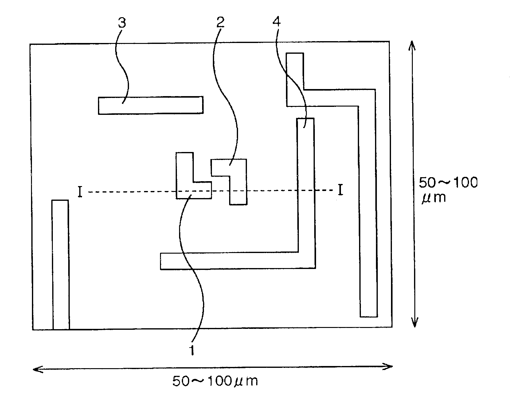
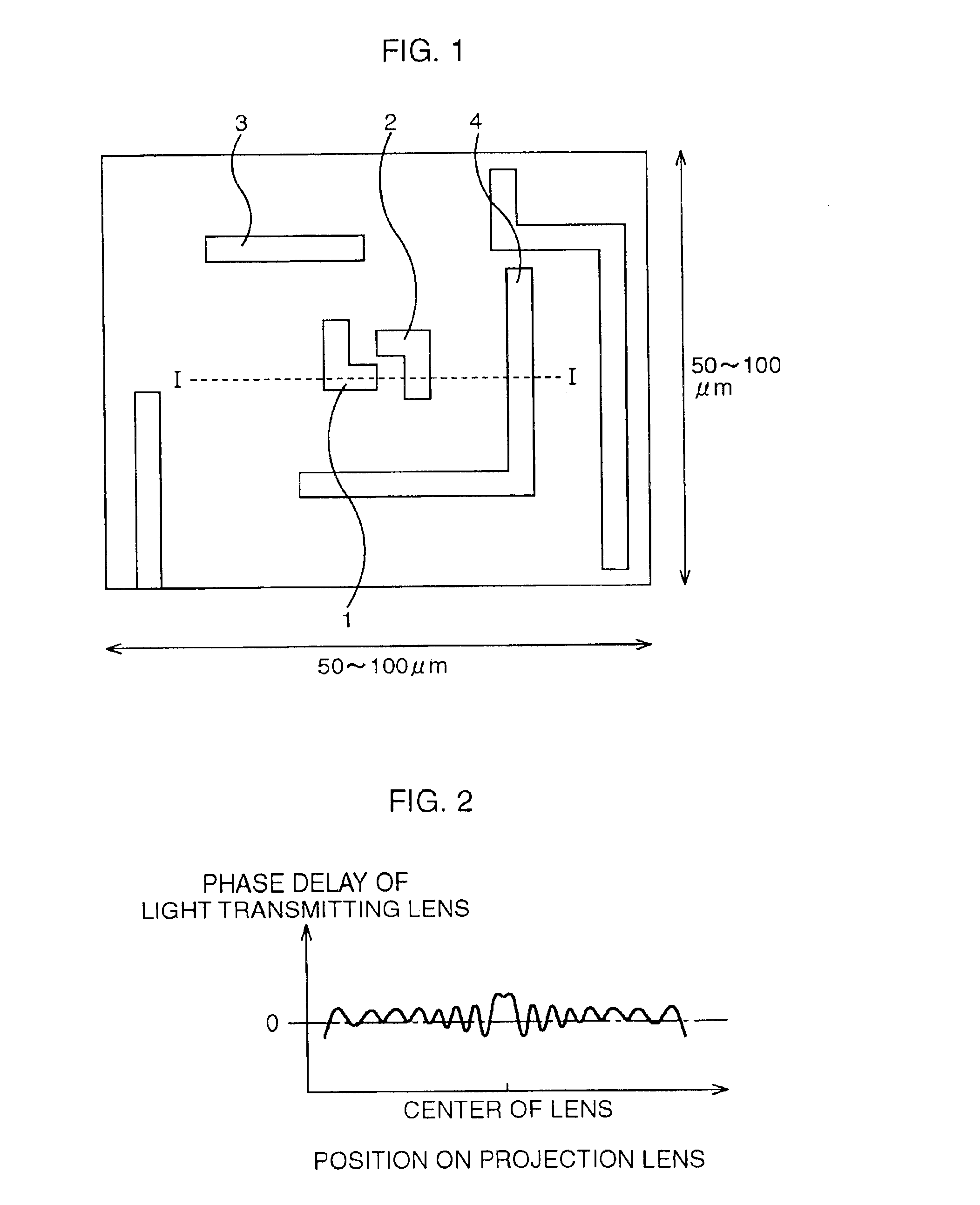
First, a light intensity simulation method according to a first embodiment of the present invention will be explained. FIG. 1 is a schematic view showing the light intensity simulation method according to the first embodiment of the present invention with respect to a photomask shown in FIG. 17.

According to this embodiment, when an exposure wavelength is 0.193 μm, a rectangular area whose side length is about 50 to 100 μm is made to be a unit of calculation in order to take influence of local flare into consideration, as shown in FIG. 1. This is because the influence of the local flare by a pattern in a mask is within the limit of about 50 μm from the pattern. As described above, according to the conventional method, the rectangular area whose side length is about 2 to 10 μm is made to be the unit of calculation, and hence it is impossible to take the influence of the local flare into account sufficiently.

According to this embodiment, an aberration of a projection lens is approximat...

second embodiment

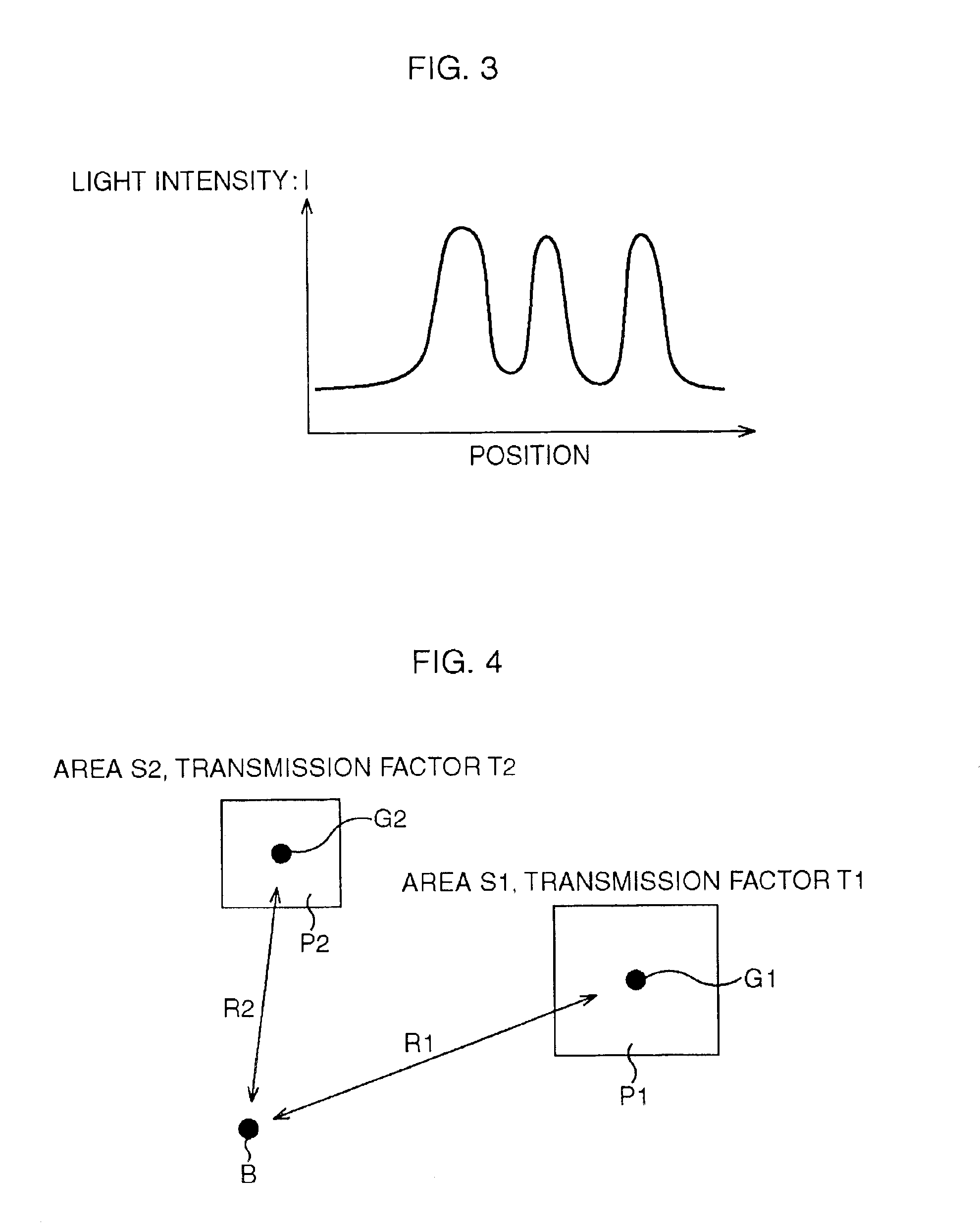
Next, a light intensity simulation method according to a second embodiment of the present invention will be explained. According to the second embodiment, the influence of the local flare is estimated based on a shape of a photomask, not on the aberration of the lens. FIG. 4 is a schematic view showing a principle of the light intensity simulation method according to the second embodiment of the present invention.

In a photomask shown in FIG. 4, it is supposed that only opening patterns P1 and P2 are formed. Further, it is supposed that an area and a transmission factor of the opening pattern P1 are S1 and T1, respectively, and an area and a transmission factor of the opening pattern P2 are S2 and T2, respectively. According to this embodiment, as shown in FIG. 4, the light intensity at a light intensity calculation point B on the photomask is found approximately based on a distance R1 from a barycenter G1 of the opening pattern P1, a distance R2 from a barycenter G2 of the opening p...

third embodiment

Next, a light intensity simulation method according to a third embodiment of the present invention will be explained. According to the third embodiment as well, the influence of the local flare is estimated based on a shape of a photomask, not on the aberration of the lens. However, an estimation method is different from that of the second embodiment. FIG. 8 is a schematic view showing a principle of the light intensity simulation method according to the third embodiment of the present invention.

In a photomask shown in FIG. 8, it is supposed that only opening patterns Q1 to Q3 are formed. According to this embodiment, a pattern occupying factor ρC, as expressed by the following expression 3, is defined with respect to a light intensity calculation point C on the photomask.

ρC=(ΣTn) / (Wx×Wy)  Expression 3

Here, Tn is an area of a part of an opening pattern Qn existing inside a rectangular region 5 whose length in an x direction on the photomask is Wx and whose length in a y direction on...


PUM

PropertyMeasurementUnit
side lengthaaaaaaaaaa
lengthaaaaaaaaaa
lengthaaaaaaaaaa

Abstract

Light intensities at light intensity calculation points on the photomask are found approximately based on distances from barycenters of opening patterns, and areas and transmission factors of the opening patterns. Thereafter, the result is added to a distribution of light intensity which is obtained by the conventional simulation without consideration given to the influence of the local flare. According to such a method, it is possible to easily carry out the simulation of the light intensity with high accuracy.

Description

CROSS-REFERENCE TO RELATED APPLICATIONSThis application is based upon and claims the benefit of priority from the prior Japanese Patent Application No. 2002-224038, filed on Jul. 31, 2002, the entire contents of which are incorporated herein by reference.BACKGROUND OF THE INVENTION1. Field of the InventionThe present invention relates to a light intensity simulation method, a light intensity simulation program product, a recording medium and a designing method of a photomask which is used in photolithography in manufacturing a semiconductor device and the like.2. Description of the Related ArtIn manufacturing the semiconductor device and the like, various patterns formed in the photomask are transferred to a photosensitive resist formed on a substrate by photolithography. After this transfer, the photosensitive resist is developed, and processing of a wiring layer or the like is carried out using the patterns of the photosensitive resist as masks. In such photolithography, a project...

Claims


Application Information

Patent Timeline
Patent Type & Authority Patents(United States)
IPC IPC(8): G03F7/20G03F1/36G03F1/68H01L21/027
CPCG03F7/70941G03F7/705
Inventor FUTATSUYA, HIROKIOSAWA, MORIMI
Owner FUJITSU SEMICON LTD
Why Eureka
Try Eureka