
Heat pump and air conditioning system for a vehicle

a technology for heating pumps and vehicles, applied in the direction of domestic cooling apparatus, lighting and heating apparatus, machine operation modes, etc., can solve the problems of flash fogging, system less and less heating efficiency, and inability to provide heat, so as to minimize the cost of components, reduce the additional cost of the system, and improve the cooling effect.

Inactive Publication Date: 2005-03-08
HANON SYST
View PDF40 Cites 106 Cited by
  • Summary
  • Abstract
  • Description
  • Claims
  • Application Information

AI Technical Summary

Benefits of technology

The present invention is a heating and cooling system for vehicles that can operate in a conventional air conditioning mode and a heat pump mode to provide supplemental heating when the conventional system is not up to an effective operating temperature. The system includes a coolant loop with a coolant outlet line and a coolant inlet line, a heater core, a first coolant / refrigerant heat exchanger, and a first coolant valve for selectively directing flow of coolant from the coolant outlet line to the coolant inlet line through the heater core and the first coolant / refrigerant heat exchanger. The system also includes a refrigerant loop with a compressor, a first refrigerant valve for selectively directing the flow of refrigerant from the compressor outlet to one of a condenser and the second coolant / refrigerant heat exchanger, a first refrigerant path, a second refrigerant path, and a second expansion device between the second coolant / refrigerant heat exchanger and the first coolant / refrigerant heat exchanger. The system can operate in all three modes, with the advantages of heat pump operation, while minimizing additional costs over a conventional HVAC system.

Problems solved by technology

The drawback with this is that the heater core will not provide heat until the engine has caused the coolant to warm up.
Now, however, newer engines and powertrain arrangements are being developed where the engine does not produce as much excess heat for the coolant to absorb.
But these systems become less and less efficient for heating as the heat source temperature becomes colder.
Moreover, since these types of combination air conditioning / heat pump systems employ the air conditioning system evaporator as a condenser in heat pump mode, there can be a flash fogging concern that occurs when the system is switched from operating in the air conditioning mode to operating in the heat pump mode.
That is, when operating in the air conditioning mode, water may condense on the evaporator.
Blowing the humid air on the windshield can possibly cause fogging on a cold windshield, which is generally disliked by vehicle occupants.
Another limitation to the air conditioning / heat pump types of systems is that they need to be capable of performing this additional function—over and above a conventional vehicle HVAC system—while minimizing the additional cost of such a system.

Method used


Image

  • Heat pump and air conditioning system for a vehicle
  • Heat pump and air conditioning system for a vehicle
  • Heat pump and air conditioning system for a vehicle

Examples


Embodiment Construction

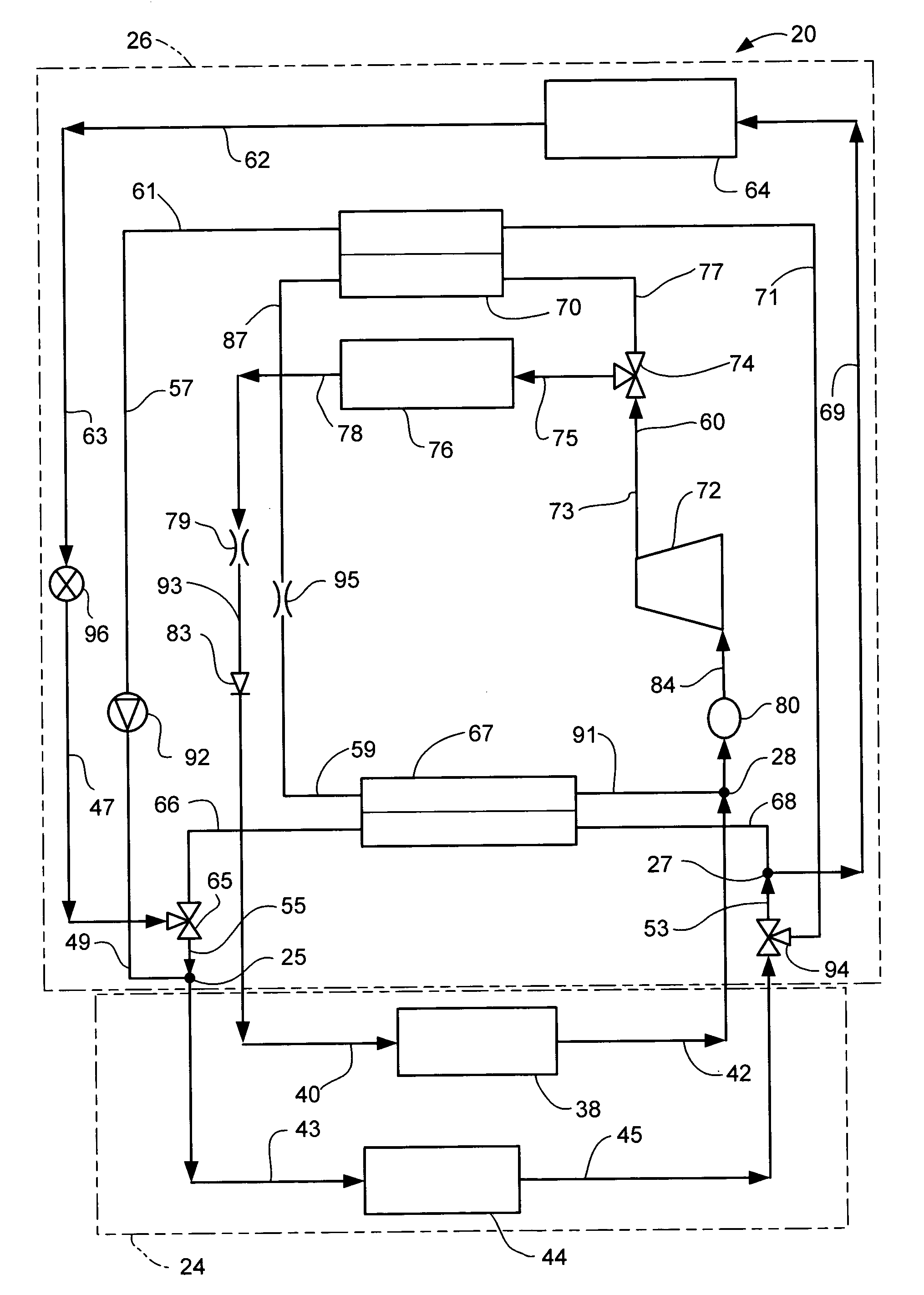
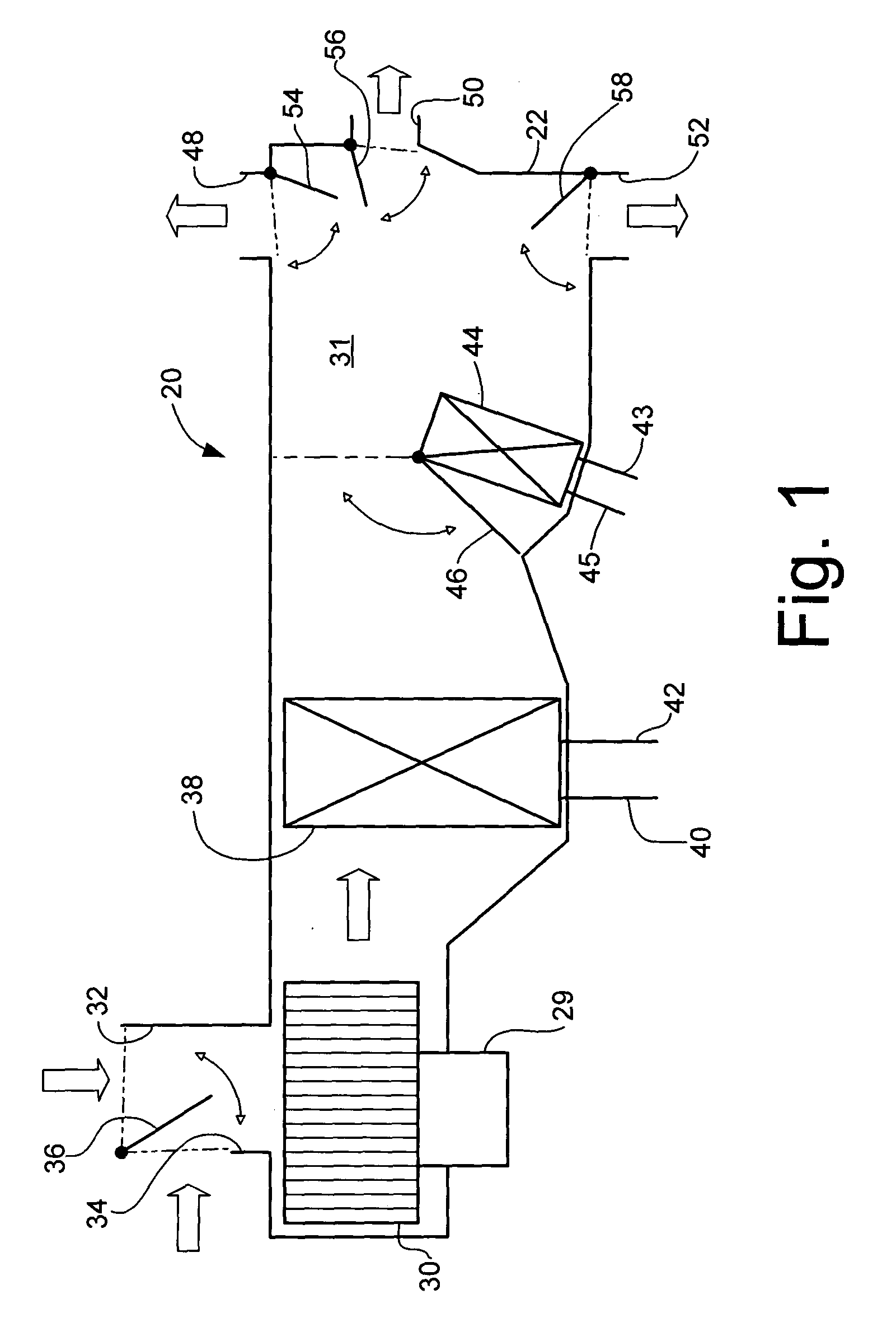
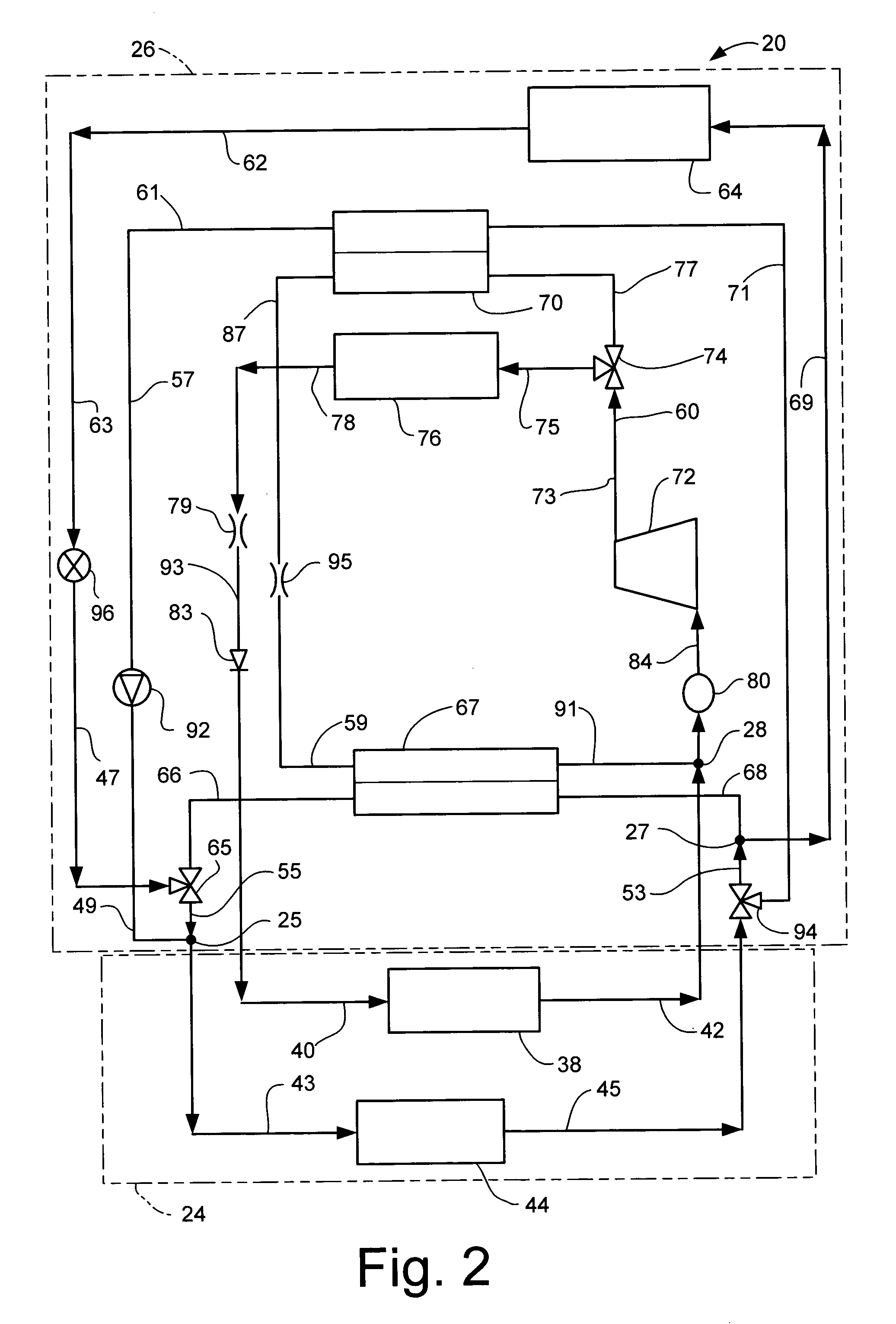
FIGS. 1-3 illustrate a vehicle heating and cooling system 20 that is partially located behind an instrument panel 22 in a vehicle passenger compartment 24, and partially in a vehicle engine compartment 26. The system 20 includes a blower 30, driven by a motor 29, and mounted in an air passage 31 in the passenger compartment 24. The blower 30 is located adjacent to an external air inlet 32, an internal air inlet 34, and an air mixing damper 36 that can be moved to partially or fully block off the external air inlet 32 or the internal air inlet 34 from the air passage 31.

Also located in the air passage 31, near the blower 30, is an evaporator 38. The evaporator 38 includes a pair of refrigerant lines 40 and 42 for directing refrigerant into and out of it. The refrigerant in the lines 40, 42 may be any type of refrigerant found in air conditioning or refrigeration systems, such as, for example, R134a. The evaporator 38 is an air / refrigerant heat exchanger.

A heater core 44 is located i...


PUM


Abstract

A heat pump and air conditioning system for a vehicle that has at least one coolant loop selectively connecting an engine cooling system with a heater core, a first coolant / refrigerant heat exchanger, and / or a second coolant / refrigerant heat exchanger, in order to warm a passenger compartment of the vehicle. The system also includes a refrigerant loop that includes a first expansion device between a condenser and evaporator, and a second expansion device between the first coolant / refrigerant heat exchanger and the second coolant / refrigerant heat exchanger. The refrigerant loop provides for cooling of the passenger compartment of the vehicle, as well as operating as a heat pump, together with the at least one coolant loop, to provide heat to the vehicle passenger compartment.

Description

BACKGROUND OF INVENTION The present invention relates to heating, ventilation and air conditioning (HVAC) systems for vehicles, and in particular to such systems having dual modes for providing heat to passenger compartments of the vehicles. In a conventional automotive vehicle employing an internal combustion engine, the heating of the passenger compartment is accomplished by running engine coolant, typically a mix of water and glycol (antifreeze), through a heater core in the passenger compartment, and then blowing air over the heater core and onto the passengers. The drawback with this is that the heater core will not provide heat until the engine has caused the coolant to warm up. For most conventional engines, this time to warm up the coolant is sufficiently short to satisfy the vehicle passengers. Now, however, newer engines and powertrain arrangements are being developed where the engine does not produce as much excess heat for the coolant to absorb. Some examples are a direc...

Claims


Application Information

Patent Timeline
Patent Type & Authority Patents(United States)
IPC IPC(8): B60H1/00F25B29/00
CPCB60H1/00878B60H1/00892F25B29/003B60H2001/00935B60H2001/00949B60H2001/00928
Inventor MEYER, JOHN J.ZHANG, CHAO A.YANG, ZHAOLI G.PAPOULIS, EVANGELOS
Owner HANON SYST
Learn More