Tape tension controlling mechanism for magnetic recording/reproducing apparatus

Inactive Publication Date: 2005-03-08
PANASONIC CORP
View PDF7 Cites 0 Cited by
  • Summary
  • Abstract
  • Description
  • Claims
  • Application Information

AI Technical Summary

Benefits of technology

In still another embodiment of the present invention, a protrusion for supporting the tension band is provided at a predetermined position in the magnetic recording / reproducing apparatus such that the tension band is prevented from moving toward the threaded portion of the band fixing screw even when the longitudinal position of the band fixing screw is shifted by rotating the band fixing screw.
Thus, the invention described herein makes possible the advantages of providing an inexpensive, small sized tension controlling mechanism for use in a magnetic recording / reproducing apparatus, wherein: the position of a tension post can be adjusted by a very simple adjustment mechanism; the number of components of the tape tension controlling mechanism is small; adjustment performed during an assembly process of the tension controlling mechanism is readily achieved with a small number of steps; and the adjustment mechanism consumes a small space.

Problems solved by technology

However, without the provision of an adjustment mechanism, it is difficult to accurately position the tension post 14 due to variations in the sizes of the various elements described above.
However, the above structure involves the problems described below.
Further, the position of the tension post 14 is merely adjusted by trial-and-error while the screw is loosened, where during tightening the screw it is easy for the tension post 14 to move from the predetermined position, such that accurate positioning of the tension post 14 is not possible.
Thus, in the conventional tape tension control mechanism, a large number of components are used; the adjustment performed during an assembly process is complicated and includes many steps; and it is difficult to reduce the size of the entire mechanism because an adjustment mechanism consumes a large space.

Method used


Image

  • Tape tension controlling mechanism for magnetic recording/reproducing apparatus
  • Tape tension controlling mechanism for magnetic recording/reproducing apparatus
  • Tape tension controlling mechanism for magnetic recording/reproducing apparatus

Examples


Embodiment Construction

Hereinafter, an embodiment of the present invention will be described with reference to FIGS. 1 through 4.

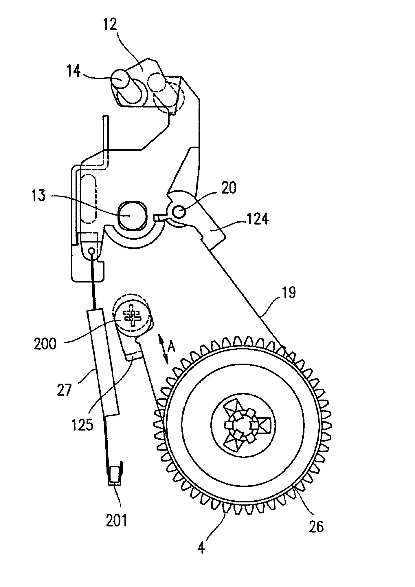
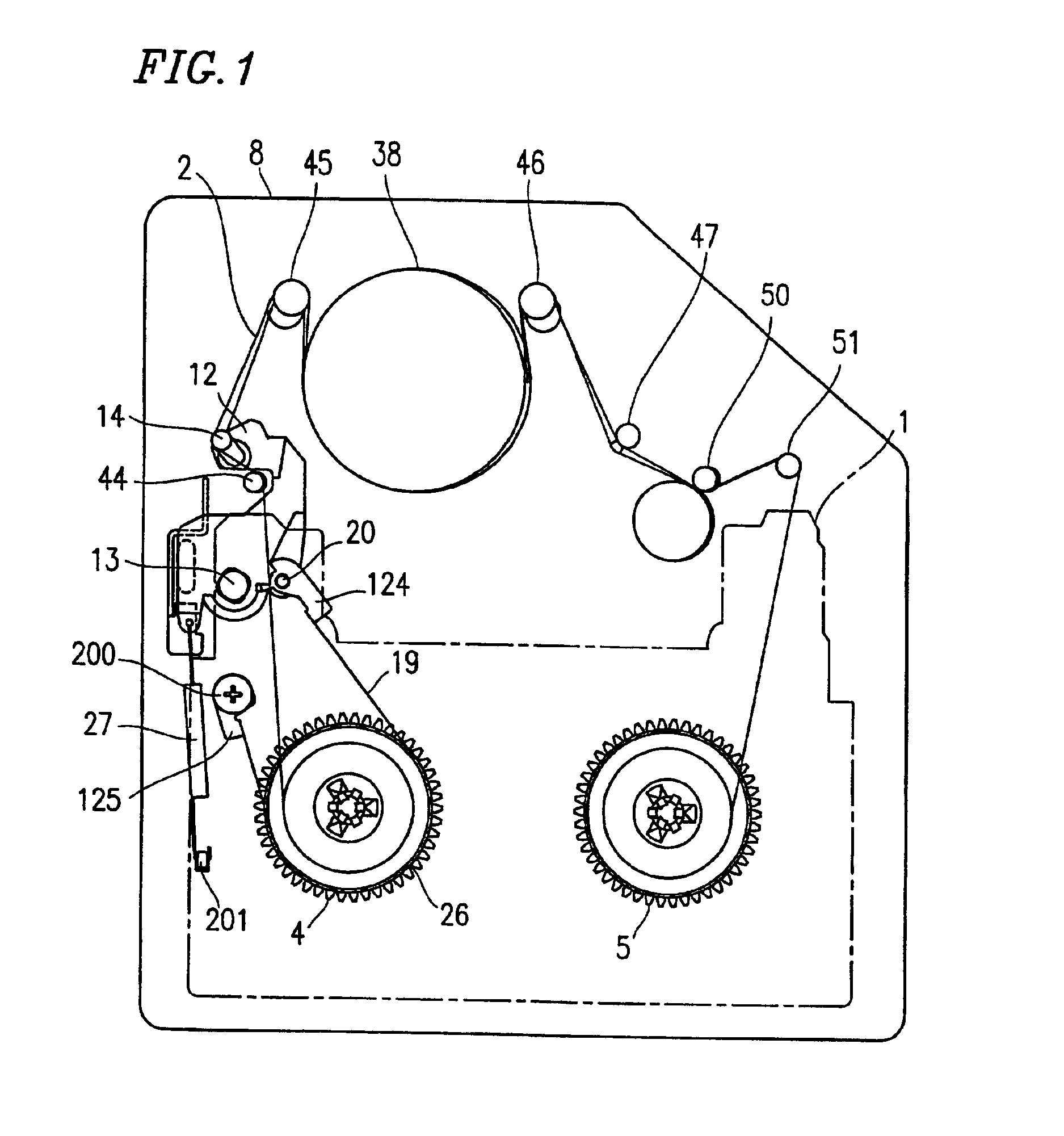
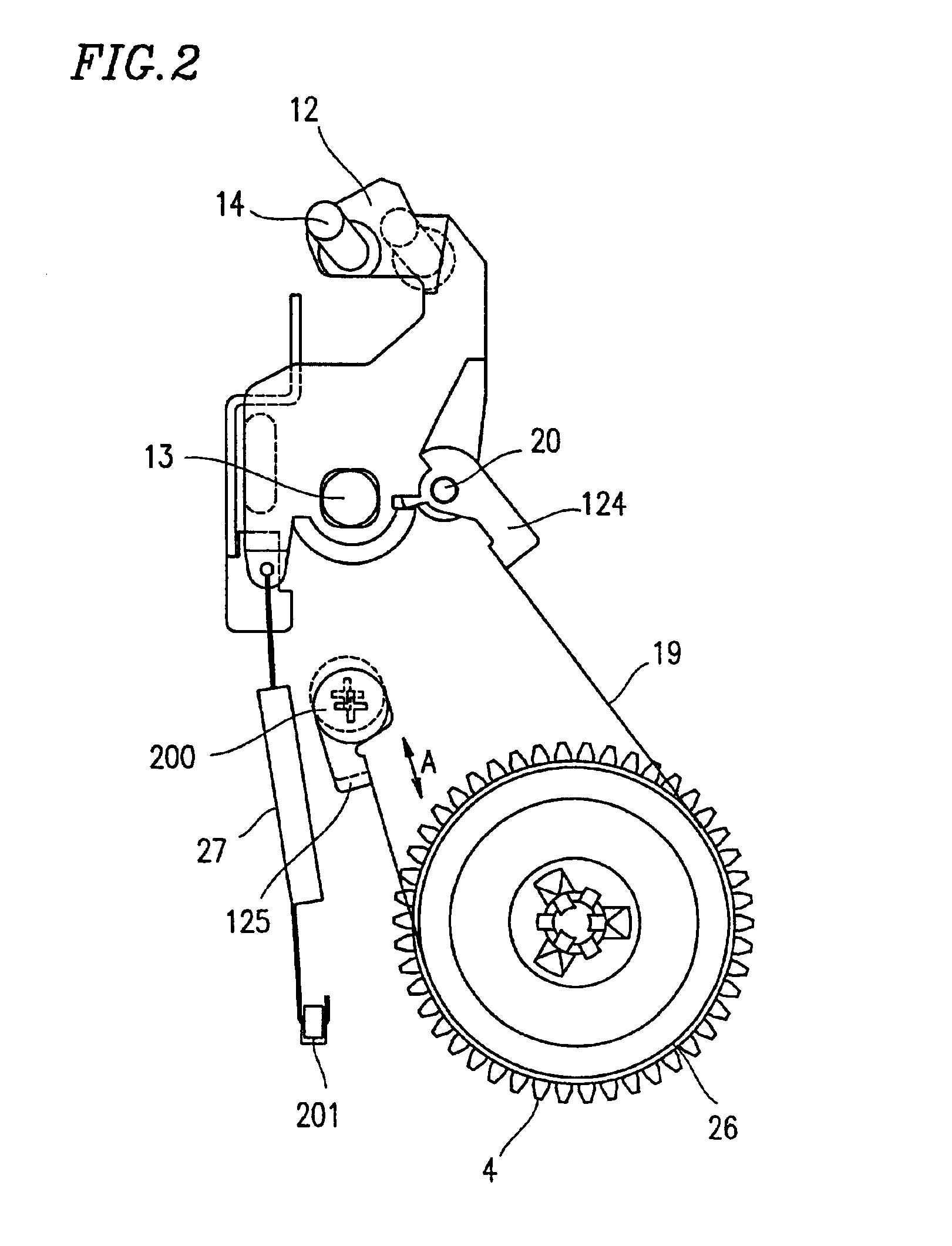
FIG. 1 is a plan view showing a mechanism of a magnetic recording / reproducing apparatus (VTR) including a tape tension controlling mechanism according to embodiment 1 of the present invention. In FIG. 1, some components of the mechanism of the magnetic recording / reproducing apparatus are omitted for clarity of illustration.

Reference numeral 1 denotes a cassette, and reference numeral 2 denotes a magnetic tape which is tensionally looped in the cassette 1. The tape 2 is wound around two tape reels (not shown) contained in the cassette 1. For the clarity of illustration, only the outline of the cassette 1 is shown by a dashed line. Reference numeral 8 denotes a main chassis for mounting the cassette 1. Reference numerals 4 and 5 denote an S-reel bed and a T-reel bed, respectively, which are rotatably mounted on the main chassis 8. The S-reel bed 4 and T-reel bed 5 are engaged, and...


PUM


Abstract

A tape tension controlling mechanism of a magnetic recording / reproducing apparatus for controlling a tension of a magnetic tape includes: a reel bed; a reel bed drum; a tension post; a tension arm rotatably supported by a tension arm shaft; an urging element; a tension band having an engagement portion; and a band fixing screw having a threaded portion at one end thereof and a head portion at the other end, the band fixing screw further having, between the threaded portion and the head portion, an intermediate shaft portion for engagement with the engagement portion of the tension band, wherein a longitudinal center line of the intermediate shaft portion is shifted from the longitudinal center line of the threaded portion, and a pitch P of a thread of the threaded portion and a longitudinal length L of the intermediate shaft portion have a relationship of L>P / 2.

Description

BACKGROUND OF THE INVENTION1. Field of the InventionThe present invention relates to a tape tension controlling mechanism for use in a magnetic recording / reproducing apparatus, such as a videotape recorder (VTR).2. Description of the Related ArtIn recent years, there has been a growing demand for a decrease in size of magnetic recording / reproduction apparatuses, such as VTRs, camcoders, etc.A tape tension controlling mechanism for use in a conventional magnetic recording / reproducing apparatus is described below.As an example of a conventional technique for tape tension control, a mechanism disclosed in Japanese Patent Application No. 10-070169, which is incorporated herein by reference, is described with reference to FIG. 5, which is essentially equivalent to FIG. 15 of Japanese Patent Application No. 10-070169. In FIG. 5, reference numeral 1 denotes a cassette, and reference numeral 2 denotes a tape which is tensionally looped in the cassette 1. The tape 2 is wound around an S-reel...

Claims


Application Information

Patent Timeline
IPC IPC(8): G11B15/43
CPCG11B15/43
Inventor NAGASAKI, EIJIKONISHI, AKIO
Owner PANASONIC CORP
Why Eureka
Try Eureka