Ocular fixation and stabilization device for ophthalmic surgical applications

a technology for ophthalmic surgery and stabilization devices, which is applied in the field of interface devices for ophthalmic laser surgery, can solve the problems of permanent damage to non-renewable tissue within the eye, affecting the patient's overall relative motion, and imposing the burden of minimizing relative motion on the patien

Inactive Publication Date: 2005-03-08
AMO DEVMENT
View PDF11 Cites 240 Cited by
  • Summary
  • Abstract
  • Description
  • Claims
  • Application Information

AI Technical Summary

Benefits of technology

A method for applanating an anterior surface of a patient's eye and coupling the eye to a surgical laser system includes providing an interface which includes a central orifice, and is characterized by top and bottom surfaces. A suction ring is removably coupled to the bottom surface of the interface and the interface is positioned over an operative area of an eye, such that the suction ring

Problems solved by technology

However, complications surrounding the use of the microkeratome and its metal blade have resulted in research into improved techniques that are performed exclusively by a laser system.
Despite these advances in laser technology, the use of such systems for ophthalmic surgical procedures remains fraught with substantial mechanical limitations, particularly in the area of developing a stable interface between an incident laser beam and the eye of a patient.
Even a very small movement of the eye with respect to the intended focal point of the laser beam can not only lead to non-optimal results, but might even result in permanent damage to non-renewable tissue within the eye, leading to precisely the opposite result than that desired.
While this technique has provided some small benefit, it places all of the burden of minimizing relative motion upon the patient, and does

Method used


Image

  • Ocular fixation and stabilization device for ophthalmic surgical applications
  • Ocular fixation and stabilization device for ophthalmic surgical applications
  • Ocular fixation and stabilization device for ophthalmic surgical applications

Examples


Embodiment Construction

Conceptually, the present invention is directed to a mechanical apparatus that performs the functions of coupling the anterior surface of a target eye to a surgical laser and applanating said eye. The apparatus is termed mechanical because it directly couples the mechanical surface of an operative target, such as human corneal tissue, to a mechanical fixture of a surgical laser system, such as the distal tip of a laser beam's delivery system. Simply put, and in the context of a particular embodiment which will be described in greater detail below, the apparatus is affixed to the anterior surface of a human cornea and is affixed to the laser delivery system.

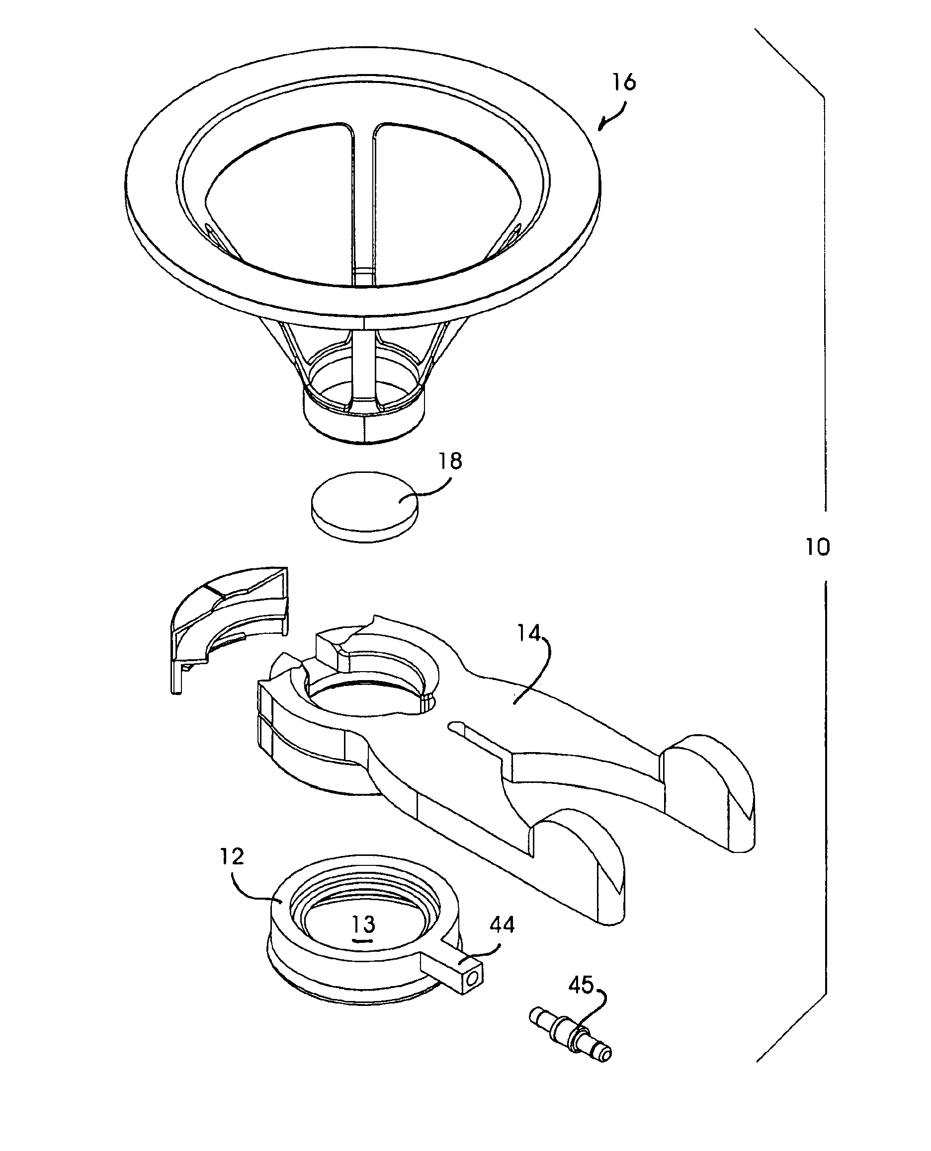
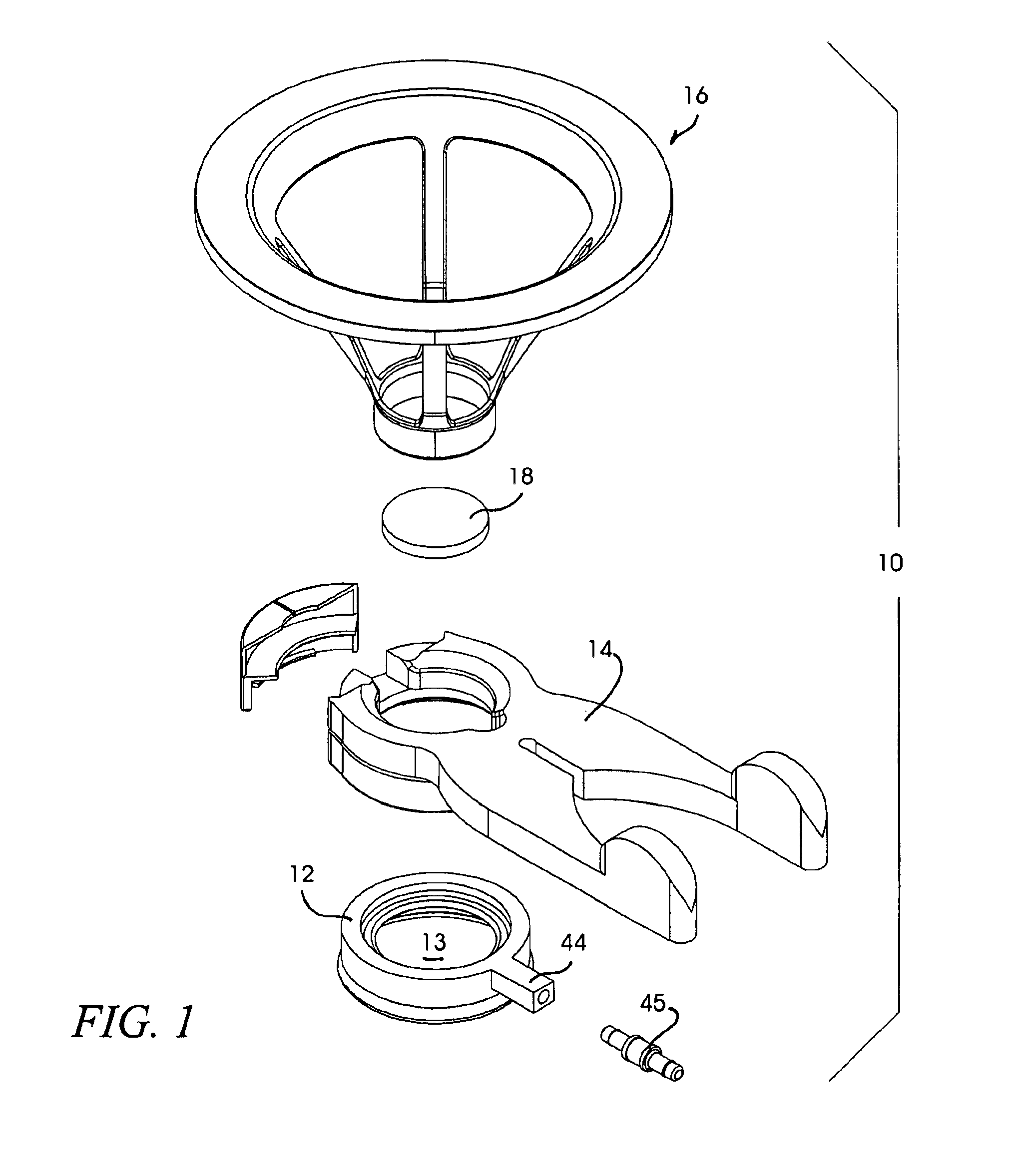
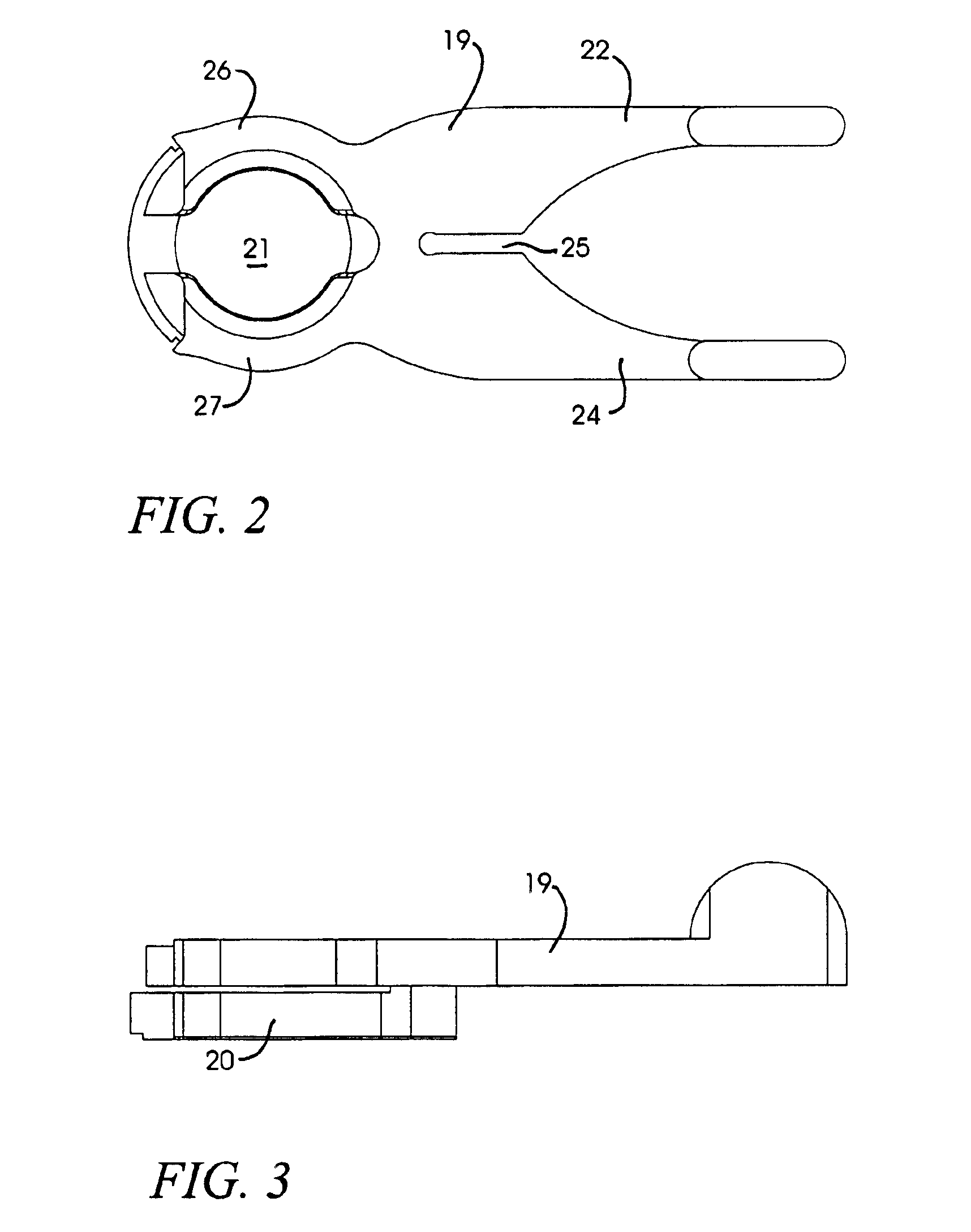
Referring initially to the exemplary embodiment of FIG. 1, an illustrative ocular fixation and applanation device is shown in an exploded, perspective view, and is generally indicated at 10. The ocular fixation and applanation device (referred to herein as simply an applanation device or alternatively, a patient interface) is an a...


PUM


Abstract

A disposable stabilization and applanation device for reconfiguring the cornea of an eye for ophthalmic laser surgery, includes an applanation lens that is disposed in a particular spatial position with respect to an incident laser beam. The applanation lens is inserted into the central opening of an attachment ring and applanates the eye in response to pressure from a lens cone. The attachment ring is coupled to the eye and includes a skirt which surrounds the applanation lens and extends outwardly therefrom to define a chamber. The skirt is formed with a groove which defines a suction channel between the attachment ring skirt and the corneal surface of an eye. A vacuum source is connected and fluid communication with the suction channel and is selectively activated to create a partial vacuum in the channel.

Description

FIELD OF THE INVENTIONThe present invention relates to an interface device for ophthalmic laser surgery and, more particularly, an interface apparatus used to stabilize the eye of a patient with respect to a laser beam during ophthalmic surgery, and to reconfigure the cornea for precision laser interaction.BACKGROUND OF THE INVENTIONIn recent years, significant developments in laser technology have led to its application in the field of ophthalmic surgery. In particular, laser surgery has become the technique of choice for ophthalmic surgical applications. In certain ophthalmic laser procedures, surgeons use a mechanical device termed a microkeratome to cut a layer of the anterior surface of the cornea in order to expose the underlying corneal stroma to which the laser is applied. However, complications surrounding the use of the microkeratome and its metal blade have resulted in research into improved techniques that are performed exclusively by a laser system. Such all-laser techn...

Claims


Application Information

Patent Timeline
IPC IPC(8): A61F9/009A61F9/007A61F9/01A61B17/30A61F9/008
CPCA61F9/009A61B2017/306A61F2009/00846A61F9/008
Inventor WEBB, KYLE R.BROWNELL, MICHAEL F.HORVATH, CHRISTOPHERJUHASZ, TIBORKURTZ, RONALD M.NAGY, LASZLO I.ROSS, MARK W.SUAREZ, CARLOS G.
Owner AMO DEVMENT
Why Eureka
Try Eureka