Deformable scaffolding multicellular stent

a multi-cellular, scaffolding technology, applied in the direction of prosthesis, surgical staples, blood vessels, etc., can solve the problems of increasing the rigidity of the stent, affecting the advancement of the stent around tight bends in the artery, and affecting the treatment of patients, so as to facilitate the advancement of the stent delivery device, facilitate the withdrawal of the elongate member, and facilitate the effect of insertion

Inactive Publication Date: 2005-03-08
MEDTRONIC VASCULAR INC
View PDF88 Cites 220 Cited by
  • Summary
  • Abstract
  • Description
  • Claims
  • Application Information

AI Technical Summary

Benefits of technology

In another aspect, the present invention is directed to a device for delivering an expandable stent, such as that previously described, to a site within a patient's body. The device includes an elongate member having proximal and distal ends, a nose cone on the distal end, and an expandable member on the elongate member proximate to the nose cone for receiving an expandable stent thereon. The nose cone has a widened portion and a tapered distal tip to facilitate insertion along a body passage.
The stent delivery device also preferably includes an outer sheath slidable over the elongate member, the outer sheath including a lumen for receiving the elongate member therethrough. The outer sheath includes a distal end having a diameter substantially similar to the widened portion of the nose cone for substantially sealing the lumen when the distal end of the outer sheath engages the widened portion of the nose c...

Problems solved by technology

The articulation provided by the hinges allows some conformity with the curvature of the vessel; however, the hinges may create gaps between the segments and/or may cause the segments to overlap one another.
Material, such as stenotic material on the vessel wall, may extend through the gaps into the vessel lumen, possibly obstructing blood flow and/or breaking loose and traveling downstream where they may cause substantial damage to the patient being treated.
Increasing the number of connectors substantially, however, may increase the rigidity of the stent, which may cause problems during stent delivery.
For example, when the stent is being delivered along a circuitous arterial path, the rigidity of the stent, particularly in its contracted condition, may impair advancement of the stent around tight bends in the artery.
The resulting connectors may deform substantially to become part of the stent structure, i.e., they may deform substantially such that they lose their flexibility and are then unable to accommodate transverse bending forces.
In addition, some known stents have substantial gaps within the individual segments themselves or between the connectors, and so may not effectively “scaffold” the underlying vessel wall, i.e., may not support the vessel wall to maintain a desired open lumen cross-sec...

Method used


Image

  • Deformable scaffolding multicellular stent
  • Deformable scaffolding multicellular stent
  • Deformable scaffolding multicellular stent

Examples


Embodiment Construction

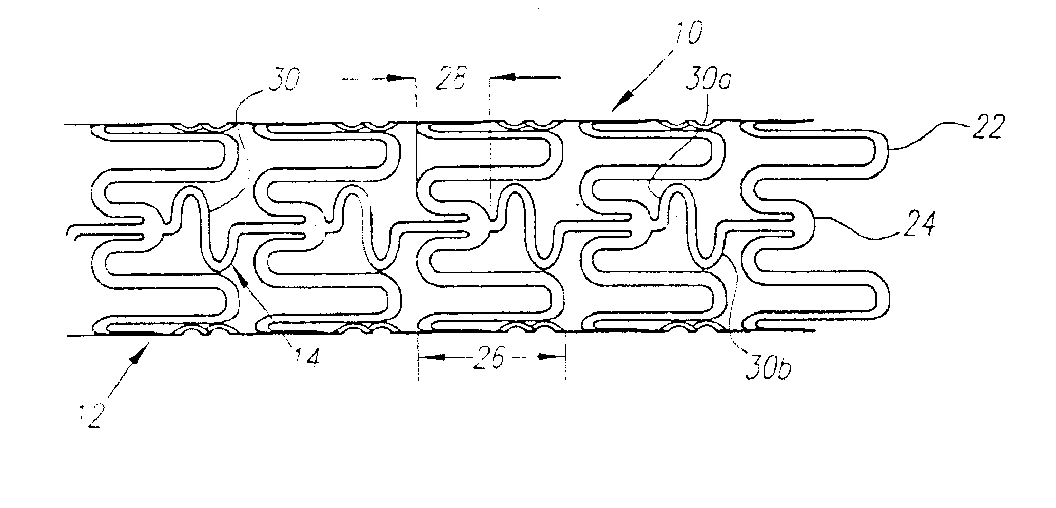
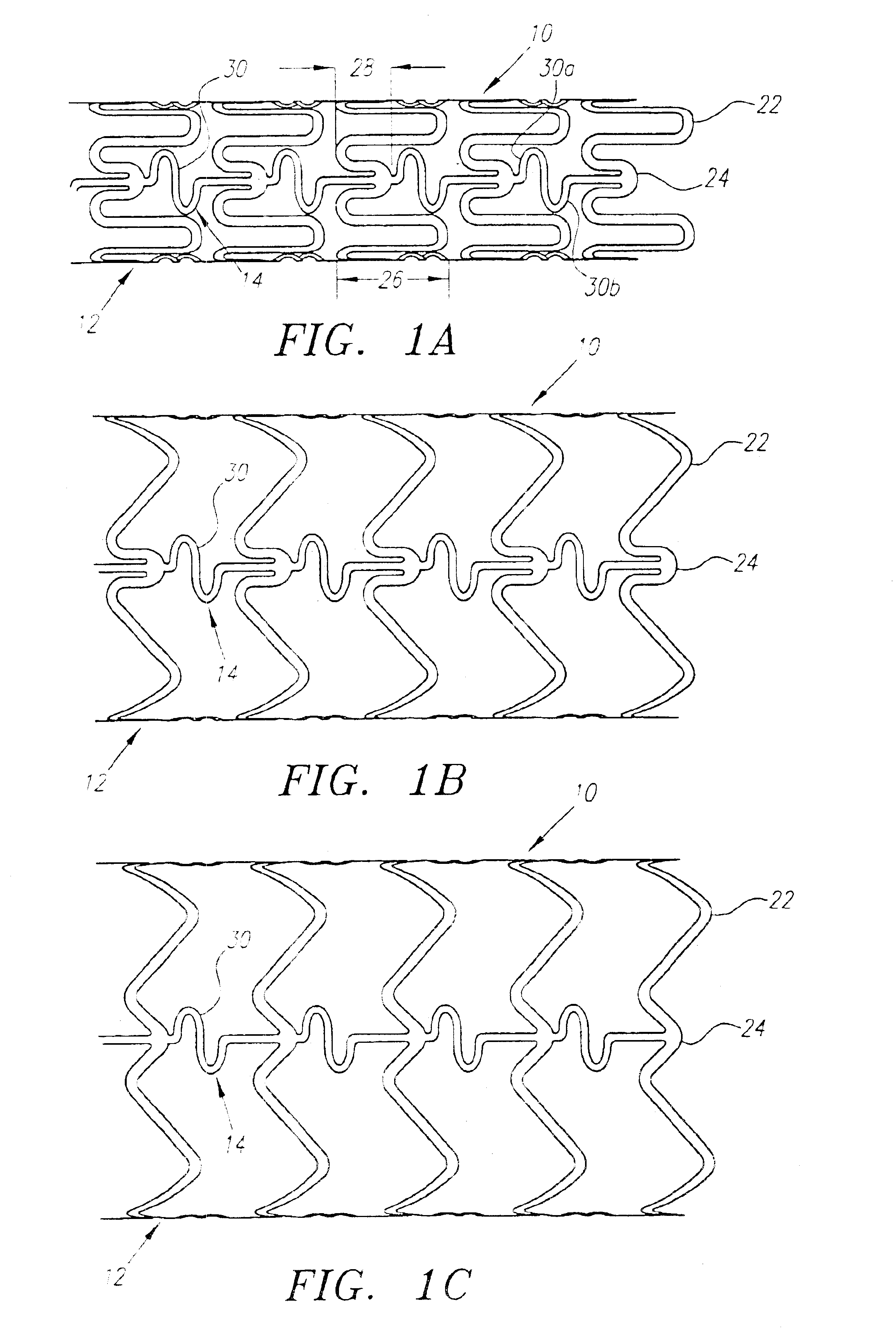
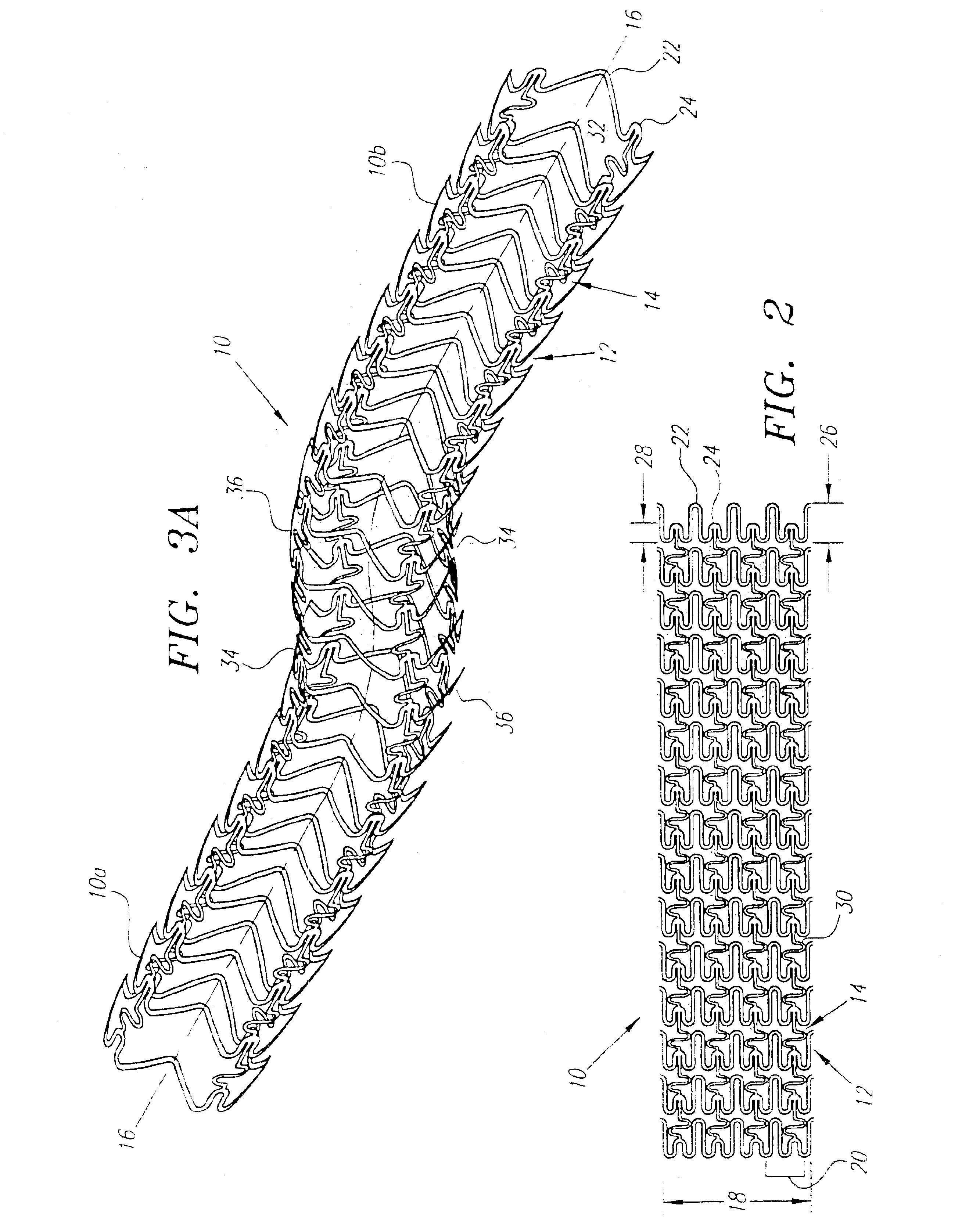
Turning now to the drawings, FIGS. 1-3 show a preferred embodiment of an implantable prosthesis or stent 10 in accordance with the present invention. Generally, the stent 10 includes a plurality of expandable cylindrical segments or “cells”12 and a plurality of articulating connectors 14 which extend between adjacent cells 12.

Preferably, the stent 10 is an initially solid tubular member, defining a longitudinal axis 16 and a circumference 18, that is preferably formed from a substantially plastically deformable material, such as stainless steel Type 316L, tantalum, MP35N cobalt alloy, or Nitinol. The walls of the tubular member are selectively removed by high precision cutting, e.g. laser cutting, chemical etching, water jet cutting or standard tool machining, to provide the pattern of cells 12 and connectors 14 described in detail below. Alternatively, the stent may be formed from a flat sheet of material that is rolled and axially fused together after creating the pattern of cells...


PUM


Abstract

A plastically deformable stent for implantation within a body passage includes a plurality of cylindrical segments, and a plurality of connectors extending between adjacent segments. Each segment has an alternating pattern of curvilinear elements extending about its circumference, including first and second sets of curvilinear elements having different resistances to expansion, and preferably defining “U” shapes with alternating lengths that are connected to one another to define a substantially sinusoidal pattern. The connectors define a sinusoidal shape adapted to extend and compress axially substantially evenly when the adjacent segments are subjected to bending. The stent may be delivered on a device including an elongate member with a nose cone, an expandable member, and a proximal shoulder thereon, and an outer sheath for slidably receiving the elongate member therein. The outer sheath and/or nose cone may have perfusion holes for allowing continued perfusion of fluid during stent delivery. The device may be used in a method for implanting a stent within a curved region of a body passage, particularly for creating and/or maintaining a channel connecting a vein to an adjacent artery, preferably in the coronary system.

Description

FIELD OF THE INVENTIONThe present invention relates generally to implantable devices for use within the cardiovascular system, and more particularly to deformable prostheses for implantation within and / or between blood vessels, and to methods of using them.BACKGROUNDA variety of stents are known for use within arteries of a patient for treating stenoses, strictures, aneurysms, and the like. For example, a stent may be implanted within a partially occluded region of an artery to retain stenotic material beneath the stent and / or to open the lumen of the artery to improve blood flow therethrough.Stents generally have a substantially cylindrical shape and are expandable between a contracted condition for facilitating delivery and an enlarged condition for engaging the vessel wall after deployment within the artery. Stents may be self-extending, i.e., they may be biased to the enlarged condition but restrained in the contracted condition during delivery, for example within a sheath. Alte...

Claims


Application Information

Patent Timeline
IPC IPC(8): A61B17/11A61F2/06A61B17/03A61B17/12A61B17/00A61B17/064A61B17/30A61B17/34A61B18/00A61B18/14A61B19/00A61F2/00A61F2/02A61F2/82A61F2/90A61M25/00A61M25/095
CPCA61B17/11A61B17/12022A61B17/12045A61B17/12109A61B17/12136A61B17/3417A61F2/064A61F2/2493A61F2/91A61F2/915A61F2/958A61B17/00491A61M2025/1052A61B18/00A61B18/1477A61B18/1492A61B19/38A61B2017/00243A61B2017/00247A61B2017/00252A61B2017/00504A61B2017/1107A61B2017/1139A61B2017/1205A61B2017/12127A61B2017/306A61B2017/347A61B2018/00392A61B2018/1425A61F2/07A61F2/90A61F2002/061A61F2002/30079A61F2002/825A61F2002/91508A61F2002/91525A61F2002/91533A61F2002/91558A61F2002/91575A61F2002/91591A61F2210/009A61F2250/0048A61M2025/0076A61M2025/009A61B17/0643A61B90/40
Inventor KIM, STEVEN W.MAKOWER, JOSHUAFLAHERTY, J. CHRISTOPHER
Owner MEDTRONIC VASCULAR INC
Why Eureka
Try Eureka