Sliding bearing and method of manufacturing the same

a technology of sliding bearings and overlays, which is applied in the direction of mechanical equipment, rotary machine parts, transportation and packaging, etc., can solve the problems that conventional sliding bearings covered with resin overlays are difficult to meet the requirements, and the use of sliding bearings has become severer, so as to achieve the effect of further improving the bond strength

Inactive Publication Date: 2005-03-08
DAIDO METAL CO LTD
View PDF9 Cites 20 Cited by
  • Summary
  • Abstract
  • Description
  • Claims
  • Application Information

AI Technical Summary

Benefits of technology

Therefore, an object of the present invention is to provide a sliding bearing which can improve the wear resistance, anti-seizure property, initial conformability and anti-cavitation property in order that the sliding bearing may cope with more severe conditions.
The invention further provides a method of manufacturing a sliding bearing comprising the steps of applying a bonding layer material to a roughened surface of a bearing alloy layer and applying heat to the bonding layer material so that the bonding layer material is hardened into a bonding layer, applying a resin surface layer composition to a surface of the bonding layer after the step of hardening the bonding layer material, the resin surface layer composition containing PBI and a solid lubricant, and heating the resin surface layer composition so that the resin surface layer composition is hardened thereby to be formed into a resin surface layer. Consequently, the bond strength can further be improved between the bearing alloy layer and the resin surface layer.

Problems solved by technology

Recently, owing to the high power and high speed of internal combustion engines, the sliding bearings have become used under severer conditions.
However, the conventional sliding bearing covered with the resin overlay has been found difficult to meet the requirement.

Method used


Image

  • Sliding bearing and method of manufacturing the same
  • Sliding bearing and method of manufacturing the same
  • Sliding bearing and method of manufacturing the same

Examples


examples 7 to 12

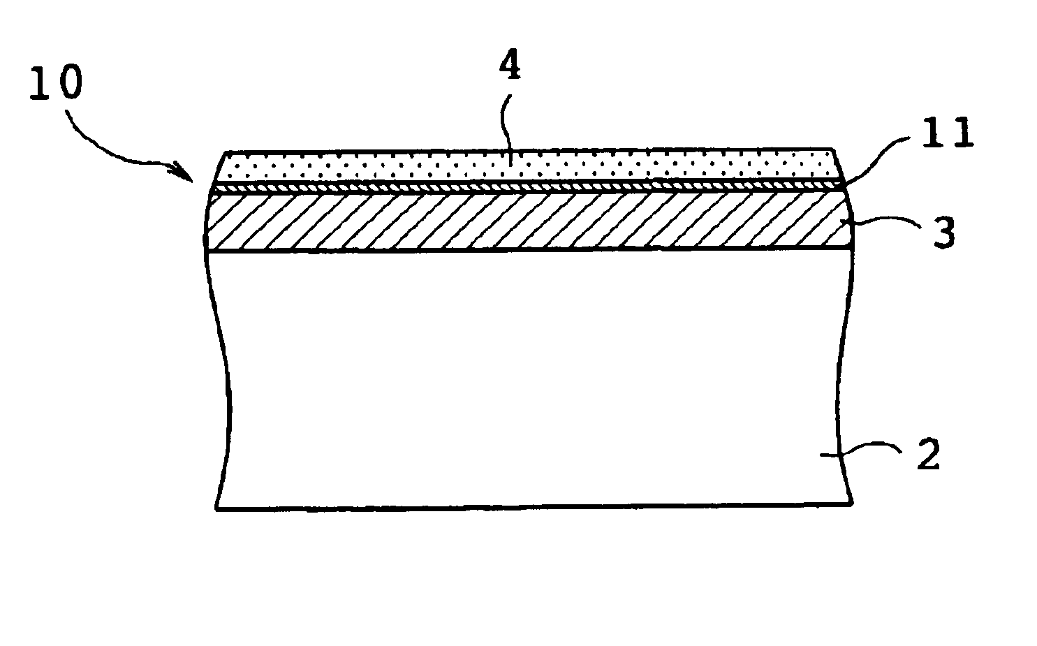
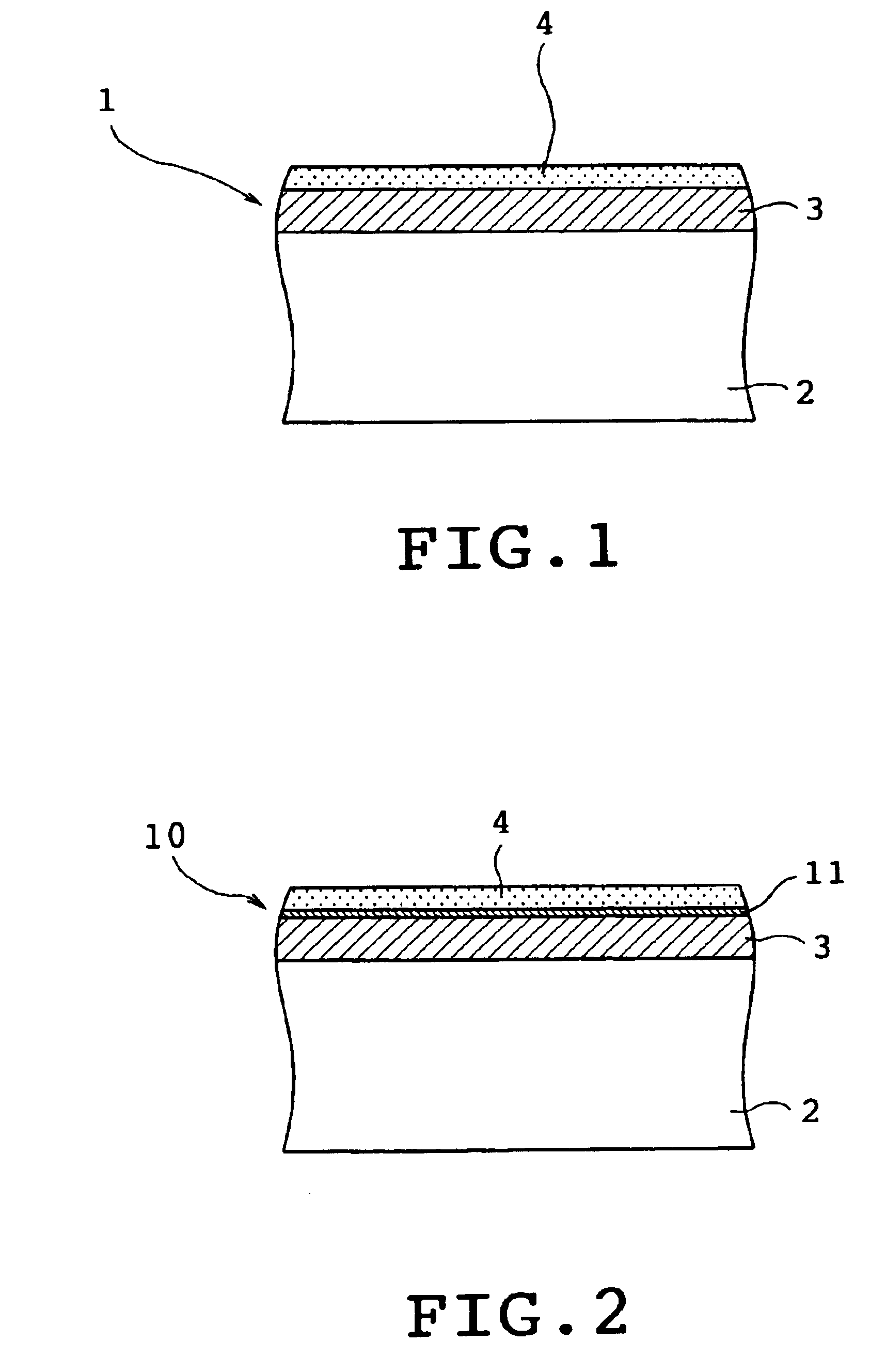
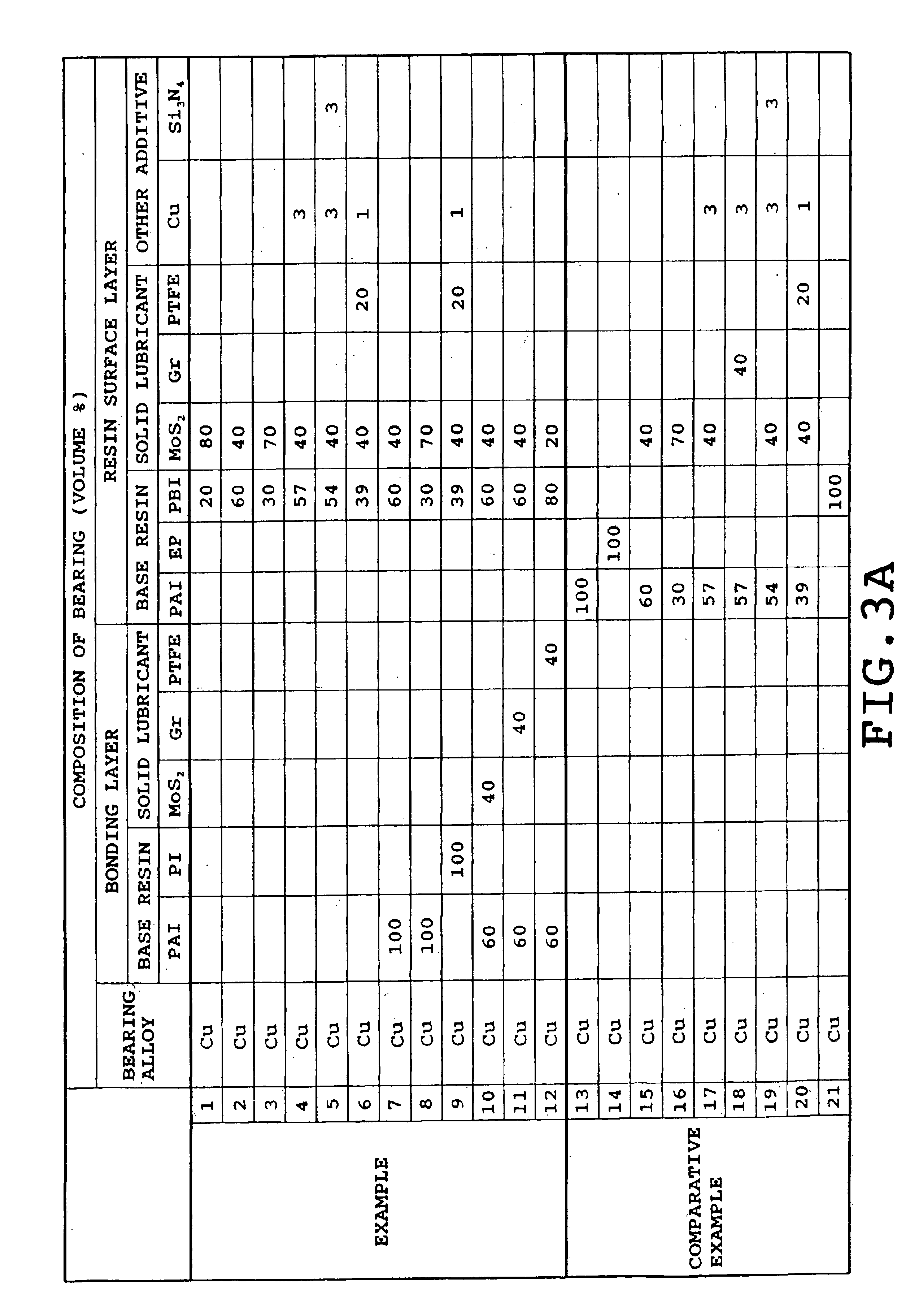
A bearing alloy layer of Cu system was bonded to a steel plate serving as a backing metal. The plate was then formed into a flat shape as shown in TABLES 2 to 4 and degreased. A surface of the bearing alloy layer was roughened by shot blasting. After acid washing, hot water washing and drying, bonding layer compositions as shown as examples 7 to 12 in FIG. 3 were sprayed on the surfaces of the bearing alloy layers by an air spray so that a thickness of 2 μm was obtained. Furthermore, the resin surface layer compositions were diluted with an organic solvent (N-dimethyl-2-pyrrolidone), and the resultant liquids were sprayed on the surfaces of the bonding layers by the air spray. Thereafter, the examples were heated at 350° C. for 60 minutes and hardened. The resin surface layer for each of the frictional wear test and cavitation test had a thickness of 18 μm, and the resin surface layer for the seizure test had a thickness of 3 μm.

FIG. 1 shows a sliding bearing of each of examples 1 t...


PUM

PropertyMeasurementUnit
thicknessaaaaaaaaaa
thicknessaaaaaaaaaa
temperatureaaaaaaaaaa

Abstract

A sliding bearing includes a bearing alloy layer having a sliding surface and a resin surface layer formed on the sliding surface of the bearing alloy layer and containing polybenzimidazole and a solid lubricant. In manufacturing the sliding bearing, a resin surface layer composition is applied to a roughened surface of a bearing alloy layer. The resin surface layer composition contains polybenzimidazole and a solid lubricant. The resin surface layer composition is heated so as to be hardened to be formed into a resin surface layer.

Description

BACKGROUND OF THE INVENTION1. Field of the InventionThis invention relates to a sliding bearing having a resin surface layer formed on a sliding surface of a bearing alloy layer and containing a resin and a solid lubricant, and a method of manufacturing the sliding bearing.2. Description of the Related ArtA sliding bearing has conventionally been used for internal combustion engines of automobiles or the like. The conventional sliding bearing includes a Cu or Al bearing alloy bonded onto a back steel. In order that a wear resistance, anti-seizure property and initial conformability may be improved, the conventional sliding bearing of the aforementioned type includes a resin surface layer formed on the surface of a bearing alloy layer so as to cover the latter layer. The resin surface layer contains a thermosetting resin such as polyamide-imide (PAI), polyimide (PI) or epoxy (EP) resin, and a solid lubricant. For example, JP-A-4-83914 and JP-A-9-79262 each disclose such improvement.R...

Claims


Application Information

Patent Timeline
Patent Type & Authority Patents(United States)
IPC IPC(8): B05D5/08C08L79/00C08L79/04F16C33/04F16C33/20
CPCB05D5/08C08L79/04F16C33/201Y10T428/256C10M2201/041C10M2201/066C10M2213/062C10M2217/0403C10N2230/06C10N2240/02C10N2250/18Y10S384/907Y10T428/259Y10T428/12556Y10T428/12569B05D5/083Y10T428/31681Y10T428/31678C10N2030/06C10N2040/02C10N2050/14F16C2202/54F16C2208/44
Inventor TANAKA, TAKUYAHIRAMATSU, NOBUTAKASHIBAYAMA, TAKAYUKI
Owner DAIDO METAL CO LTD
Why Eureka
Try Eureka