Eureka AIR delivers breakthrough ideas for toughest innovation challenges, trusted by R&D personnel around the world.

Dual-mode focal plane array for missile seekers

a focal plane array and dual-mode technology, applied in the field of dual-mode monolithic focal plane arrays, can solve the problems of boresighted alignment problems, inability to implement both active and passive systems in a single missile, and inability to use two such arrays at the same time, so as to achieve cost and size/weight/power reduction, cost effective and practical implementation, effect of reducing

Inactive Publication Date: 2005-03-08
BAE SYST INFORMATION & ELECTRONICS SYST INTERGRATION INC
View PDF21 Cites 37 Cited by
  • Summary
  • Abstract
  • Description
  • Claims
  • Application Information

AI Technical Summary

Benefits of technology

As will be appreciated, many system applications require both a passive IR and active laser sensing capability. Seekers used by interceptors and other missiles to acquire targets are of special interest to many users of weapon control systems. In general, the passive IR sensor has wider field of view (FOV) than the active laser sensor and is used for acquisition Active sensors use a smaller field of view to keep the laser transmitter power, size and weight manageable. Implementing both active and passive systems in a single missile is not always practical. Focal plane arrays tend to be one of the major cost drivers for Electro Optical sensors and using two such arrays is often times impractical if not impossible. Implementation of both active and passive sensors on one focal plane array permits their use in a missile sometimes called a kill vehicle, and reduces the cost and size / weight / power factors which would usually inhibit such a solution. Such an adaptation makes a common aperture approach cost effective and practical to implement and makes boresight problems associated with multiple focal plane arrays a non-issue.

Problems solved by technology

Implementing both active and passive systems in a single missile is not always practical.
Focal plane arrays tend to be one of the major cost drivers for Electro Optical sensors and using two such arrays is often times impractical if not impossible.
Nor need there be two different focal plane arrays, one for IR and one for laser radiation, which leads to boresighted alignment problems.

Method used


Image

  • Dual-mode focal plane array for missile seekers
  • Dual-mode focal plane array for missile seekers
  • Dual-mode focal plane array for missile seekers

Examples


Embodiment Construction

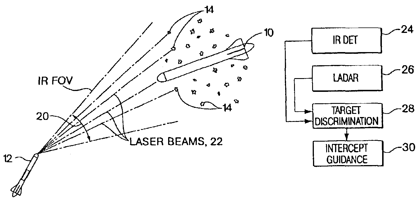
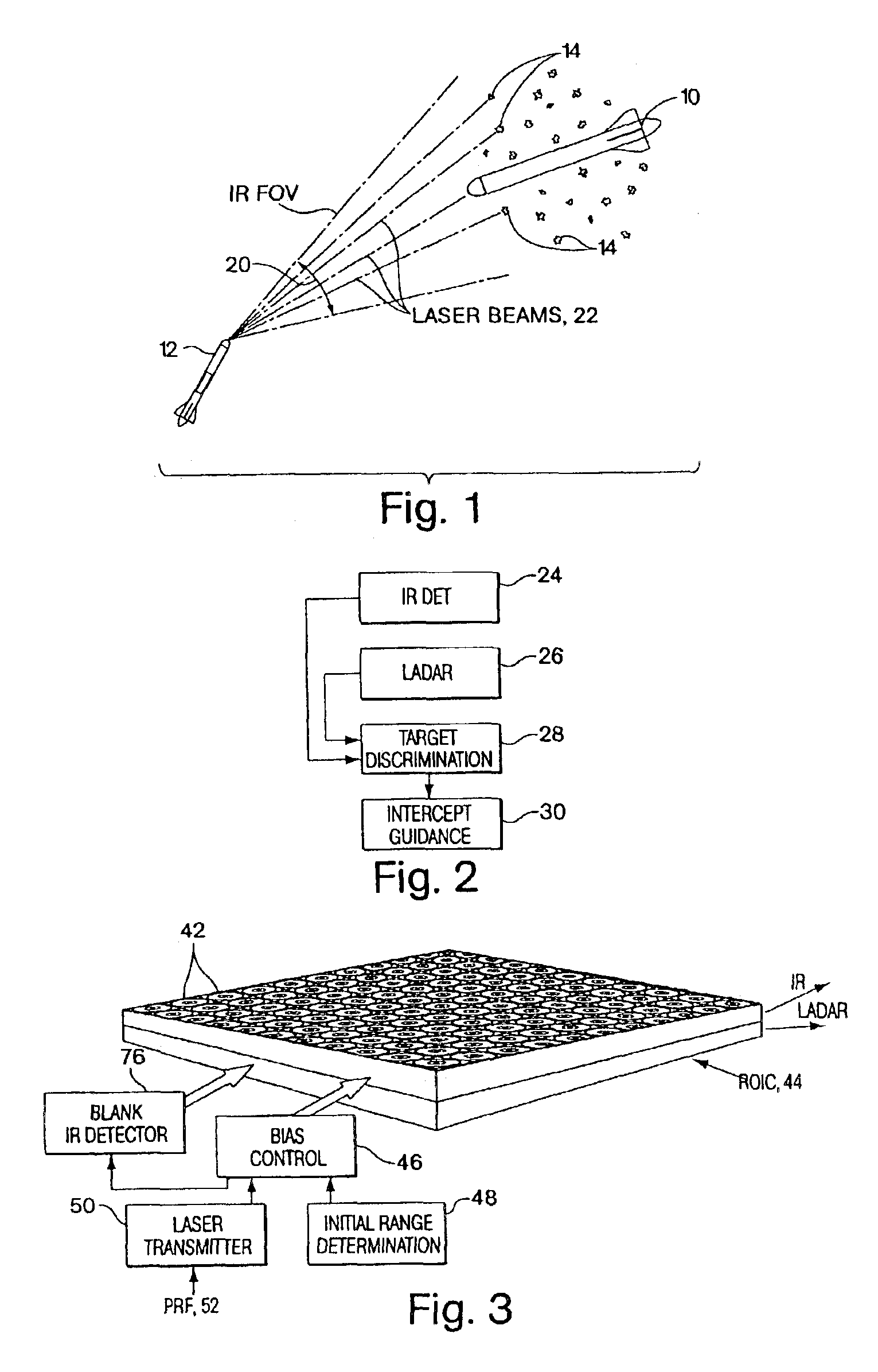
Referring now to FIG. 1, an intercept scenario is depicted in which a reentry vehicle 10 is being pursued by kill vehicle 12 which is to intercept the reentry vehicle along its trajectory. Reentry vehicle 10 deploys numerous decoys 14 to be able to prevent the kill vehicle from intercepting the reentry vehicle.

In order to ascertain the whereabouts of the reentry vehicle, infrared radiation from the reentry vehicle is sensed in a cone 20 which represents the field of view for the passive IR detector on the kill vehicle. Upon sensing of a target cloud including the reentry vehicle and decoys, the seeker is switched from a passive IR mode to an active LADAR mode in which steered laser beams 22 are directed towards the target cloud in order to be able to accurately characterize the type of target intercepted by the LADAR beam and to be able to ascertain the characteristics and track of each of the targets intercepted by the beams.

Referring to FIG. 2, the seeker on board kill vehicle 12 ...


PUM


Abstract

A single dual mode monolithic focal plane array having an active sensor and a passive sensing capability is switched from one mode to the other by switching the bias across the cells of the array from a passive IR mode to an active LADAR mode, with the monolithic dual mode focal plane array having applications in missile target seekers and laser target designators. The switching is accomplished by increasing the gain of the array by as much as 30 times that associated with IR detection when laser return pulses are expected. Thus, there need be no mechanical changes to the array to afford both passive IR sensing and an active LADAR pulse detector. Nor need there be two different focal plane arrays, one for IR and one for laser radiation, which leads to boresighted alignment problems.

Description

FIELD OF INVENTIONThis invention relates to focal plane arrays used in missile interceptors and more particularly to a dual mode monolithic focal plane array.BACKGROUND OF THE INVENTIONTarget seeking by missile interceptors can be done several ways. The most common approach uses ground-based radar for coarse guidance, then an infrared (IR) seeker for terminal guidance. IR seekers come in two varieties: passive and active. Passive sensors work with a two dimensional image and rely on the heat given off by the target for identification and tracking. This can be very effective but is subject to noise, clutter and countermeasures such as decoys. The second method uses a laser on the interceptor to scan the target. This method is very effective at shorter ranges but not suitable for acquiring targets at long distances or for scanning large volumes of space for initial target acquisition. The three dimensional (3-D) imaging capability and the single wavelength of active sensors makes them...

Claims


Application Information

Patent Timeline
Patent Type & Authority Patents(United States)
IPC IPC(8): F41G7/20F41G3/06F41G7/22F41G3/00G01J5/02G01S17/89G01S17/02G01S17/00G01S7/481G01S17/86
CPCF41G3/06F41G7/008F41G7/2246F41G7/2253F41G7/226F41G7/2293G01S17/89G01J1/4228G01S7/4816G01S17/023G01J5/0862G01J5/20G01J2005/0077G01J1/0488F41G3/145G01S17/86G01J5/0802
Inventor DEFLUMERE, MICHAEL E.
Owner BAE SYST INFORMATION & ELECTRONICS SYST INTERGRATION INC
Why Eureka
Eureka Blog
Learn More