
Reconfigurable porous technology for fluid flow control and method of controlling flow

Inactive Publication Date: 2005-03-15
ORBITAL RES
View PDF11 Cites 33 Cited by
  • Summary
  • Abstract
  • Description
  • Claims
  • Application Information

AI Technical Summary

Benefits of technology

The present invention relates to a reconfigurable porosity fluid flow control system and more particularly to reconfigurable fluid flow control system for vehicles such as aircraft, missiles, ground and water vehicles to improve the performance of such vehicles. The present invention further relates to a method of operating the reconfigurable fluid flow control system.

Problems solved by technology

These control structures have required significant payload and volume in order to house both the control structure and associated hardware imposing substantial weight, volume, and power requirements, thereby reducing the performance of the vehicle.
The additional weight and drag of these control surfaces also reduced the range and efficiency of the missile.
Furthermore, canards and fins create significant drag, pushing the missile weapons designer into a Faustian bargain, i.e., trading maneuverability and accuracy for range and payload capacity.
Similar problems exist with the use of conventional control surfaces on other types of vehicles.
Additionally, conventional control surfaces which utilize hydraulic, pneumatic, and other mechanical devices have been subject to various static and dynamic forces, loads, pressures, stresses, strain, wear and fatigue which result in reducing the life and accelerated failure of these various components.
These various static and dynamic forces, loads, pressures, stresses, strain, wear and fatigue may have been also transferred or otherwise transmitted to portions of the vehicle structure resulting in a reduction in the useful life of the vehicle structure itself.
These systems, however, have been limited from effectively operating in the changing conditions of a rapidly evolving, dynamic environment most vehicles experience during normal operations.
This is because the passive porous systems do not change in response to the highly evolving surface conditions, and the porous systems with changeable configurations are reconfigured too slowly and without the resolution (due to the small number of configurations which are achievable with these systems) needed for the fluid flow dynamics of most vehicles' surfaces.

Method used


Image

  • Reconfigurable porous technology for fluid flow control and method of controlling flow
  • Reconfigurable porous technology for fluid flow control and method of controlling flow
  • Reconfigurable porous technology for fluid flow control and method of controlling flow

Examples


Embodiment Construction

The present invention relates to a reconfigurable porosity fluid flow control system and more particularly to reconfigurable fluid flow control system for vehicles such as aircraft, missiles, ground and water vehicles to improve the performance of such vehicles. The present invention further relates to a method of operating the reconfigurable porosity fluid flow control system.

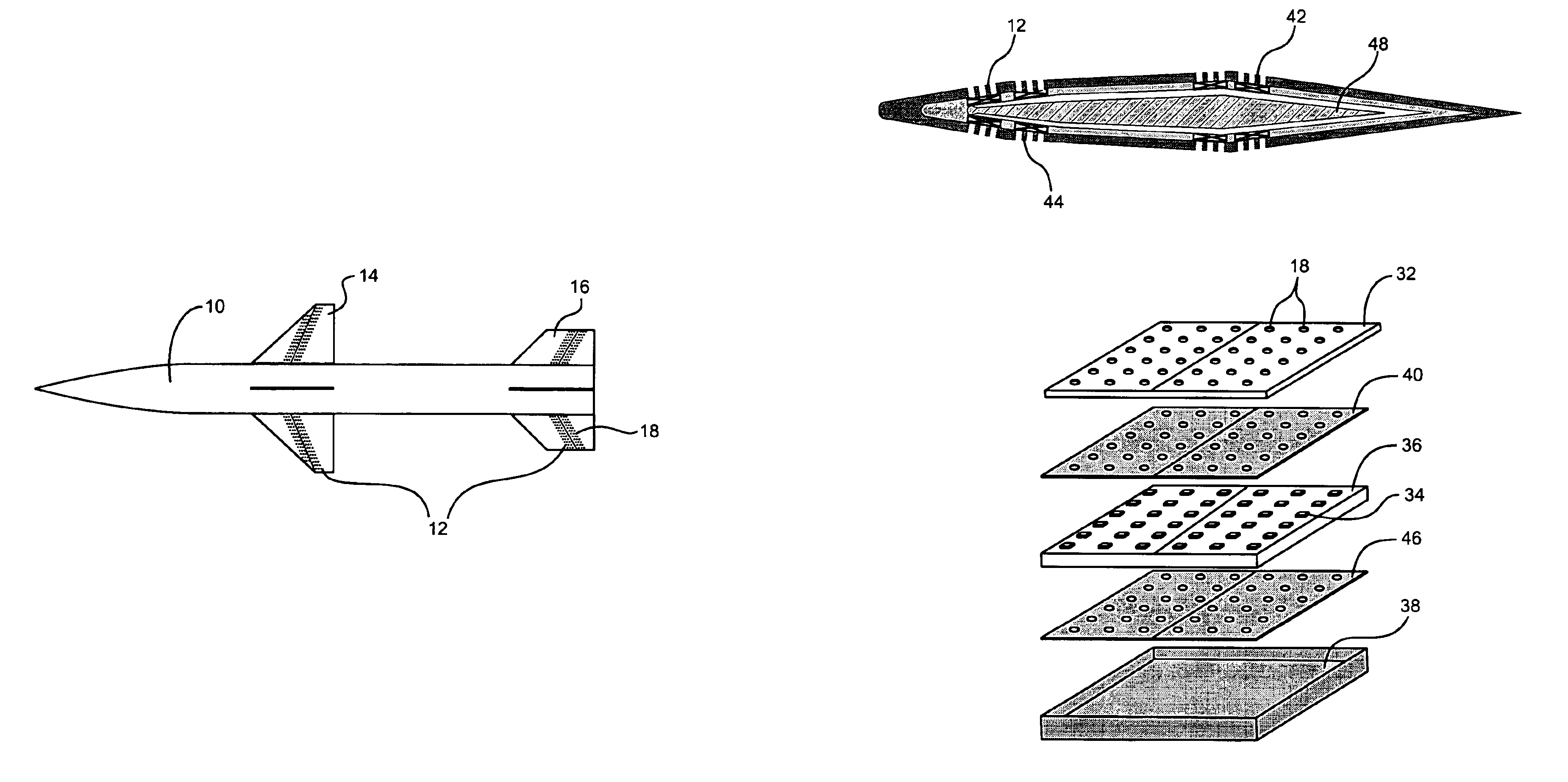
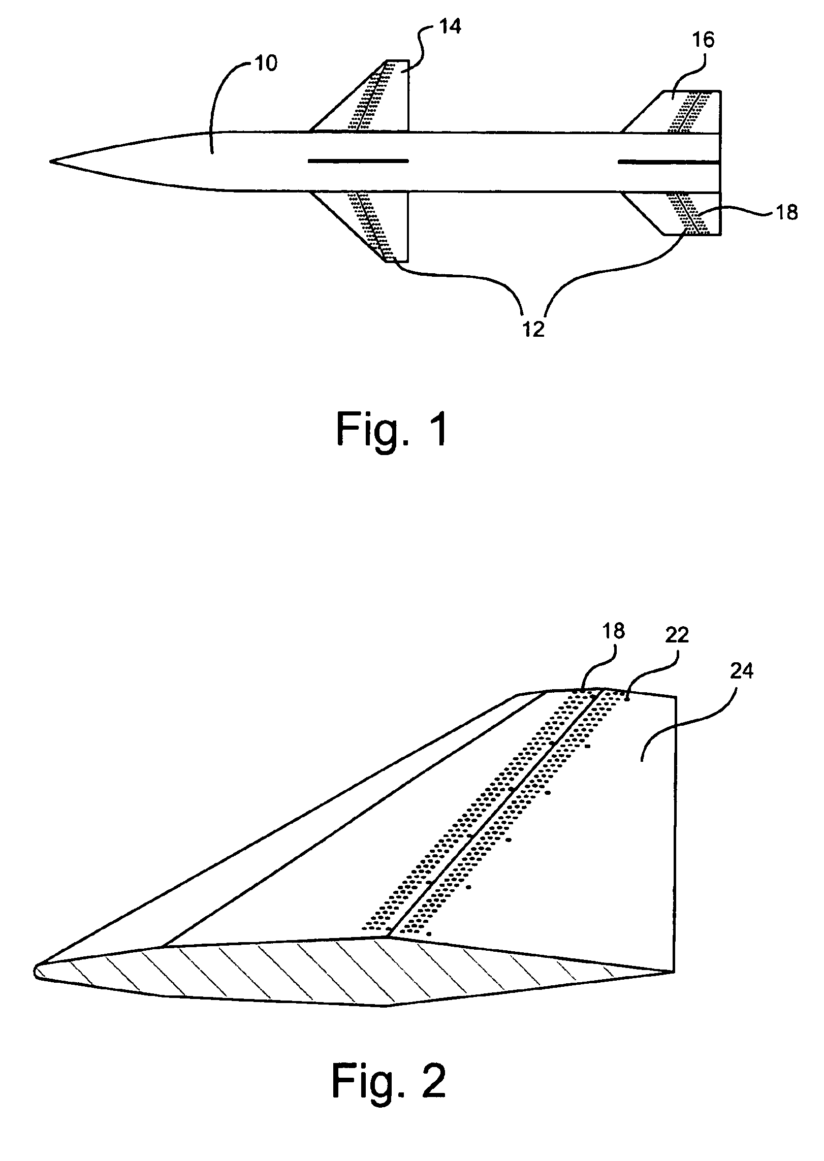
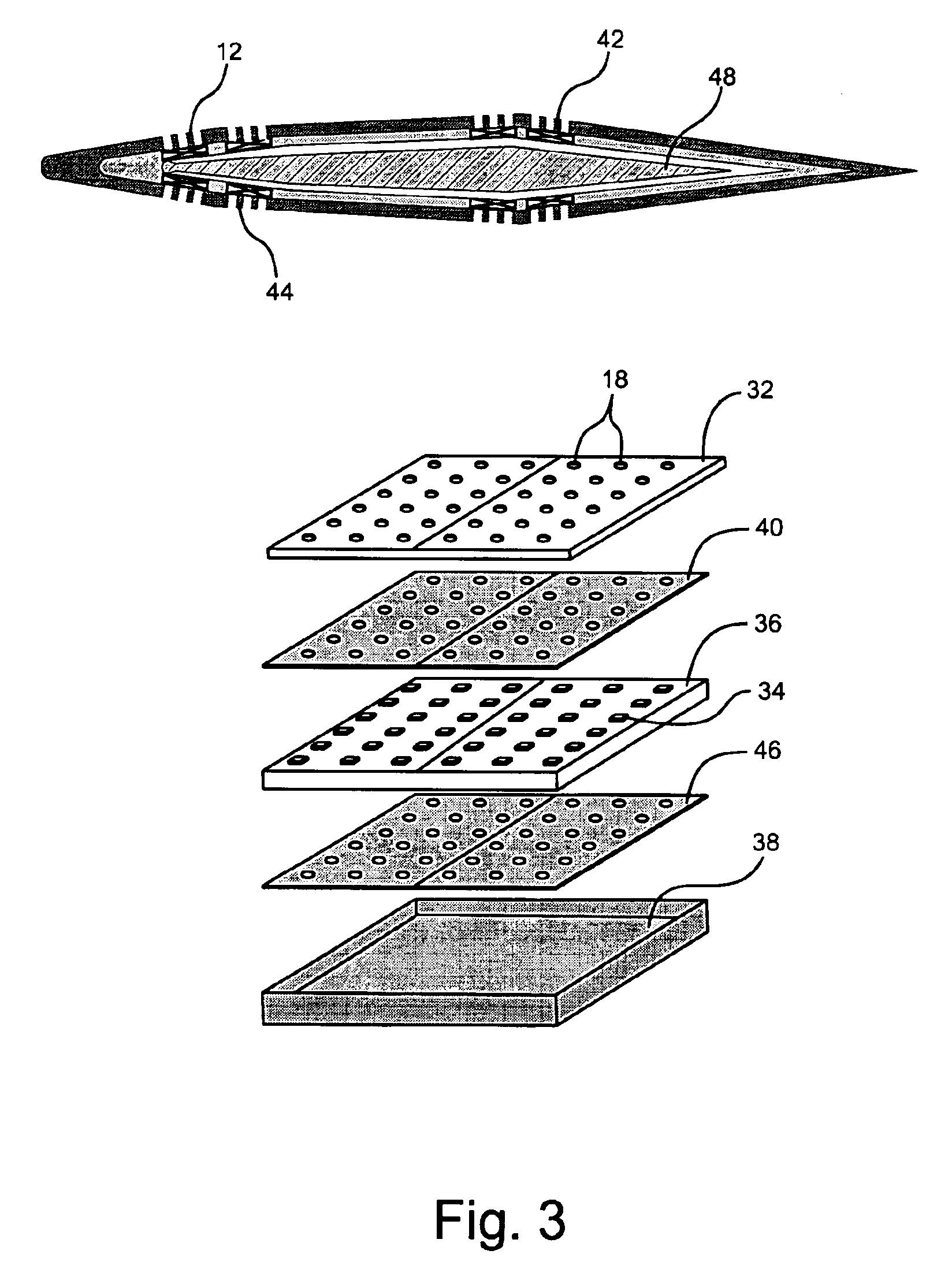
Referring now to FIG. 1, there is shown a schematic view of one embodiment of a missile 10 utilizing a reconfigurable porosity system 12 within its control wings 14 and control fins 16. The reconfigurable porosity system 12 comprising a porous skin further comprising a number of individual pores 18. The pores 18 capable of being opened and closed to the passage of fluid there through by individually addressable valves (not shown) corresponding and connected to the individual pores. The reconfigurable porosity system 12 of the present invention being used to direct fluid from high pressure areas of the porous o...


PUM


Abstract

The present invention relates to a reconfigurable porous technology for fluid flow control system and more particularly to reconfigurable porosity fluid flow control system for vehicles such as aircraft, missiles, ground and water vehicles to improve the performance of such vehicles. The present invention further relates to a method of operating the reconfigurable fluid flow control system.In one embodiment, the present invention includes a reconfigurable porosity system for fluid flow control on the surface of an aircraft, missile, water-craft or ground vehicle comprising a porous outer skin comprising individual pores; individually addressable valves corresponding and connected to the individual pores for opening and closing the pores; and a pneumatic system for connecting the pores wherein fluid from a high pressure area of the porous outer skin can be directed to a low pressure area of the porous outer skin by opening and closing the individually addressable valves. In another embodiment, the present invention includes a method of fluid flow control using reconfigurable porosity.

Description

BACKGROUND OF THE INVENTION1. Field of the InventionThe present invention relates to a reconfigurable porous technology for fluid flow control system and more particularly to reconfigurable porosity fluid flow control system for vehicles such as aircraft, missiles, ground and water vehicles to improve the performance of such vehicles. The present invention further relates to a method of operating the reconfigurable porosity fluid flow control system.2. Technical BackgroundConventionally, technology to control lift or drag on vehicles such as aircraft, missiles, ground vehicles and water vehicles utilizes various movable mechanical structures. These structures include fins, spoilers, canards and associated structural and actuation hardware to alter, vary and control lift or drag. These control structures have required significant payload and volume in order to house both the control structure and associated hardware imposing substantial weight, volume, and power requirements, thereby...

Claims


Application Information

Patent Timeline
IPC IPC(8): B64C21/00B64C21/08B64C21/02F15D1/12F15C5/00F15D1/00F16K99/00F42B10/66
CPCB64C21/025B64C21/08F15C5/00F15D1/12F16K99/0001F16K99/0051F42B10/668F16K99/0011B64C2230/22F16K2099/0082Y02T50/166B64C2230/06Y02T50/10
Inventor PATEL, MEHUL P.DICOCCO, JACK MPRINCE, TROY
Owner ORBITAL RES
Learn More