Low-loss inductive couplers for use in wired pipe strings

Inactive Publication Date: 2005-03-15
SCHLUMBERGER TECH CORP
View PDF30 Cites 219 Cited by
  • Summary
  • Abstract
  • Description
  • Claims
  • Application Information

AI Technical Summary

Benefits of technology

The invention provides a family of low-loss inductive couplers for use in wired pipe strings. The invention provides two groups of embodiments, flux-loop embodiments and current-loop embodiments.
A first embodiment includes a first flux-loop inductive coupler element with a ring-like first core having high magnetic permeability, the first core defining a first exterior substantially cylindrical face and a first interior conical-section annular face.
The first interior face defines a first interior conical-section annular larger-diameter face (herein below referred to as “first larger-diameter face”), a first interior conical-section annular smaller-diameter face (herein below referred to as “first smaller-diameter face”), and an annular first groove. The first groove is located between the first larger-diameter face and the first smaller-diameter face. The first element further includes a first electrically conductive coil wound within the first groove. The first embodiment further includes a second flux-loop inductive coupler element with a ring-like second core having high magnetic permeability, the second core defining a second interior substantially cylindrical face and a second exterior conical-section annular face.
The second exterior face defines a second exterior conical-section annular smaller-diameter face (herein below referred to as “second smaller-diameter face”), a second exterior conical-section annular

Problems solved by technology

Such a slow rate is incapable of transmitting the large amounts of data that are typically gathered with an LWD string.
In some cases (e.g., foamed drilling fluid), mud pulse telemetry does not work at all.
This delay significantly reduces the value of the data for real-time applications.
Also, there is a significant risk of data loss, for example, if the tool is lost in the hole.
Electromagnetic telemetry via earth path has been tried with limited success.
Acoustic telemetry through the drill pipe itself has been stu

Method used


Image

  • Low-loss inductive couplers for use in wired pipe strings
  • Low-loss inductive couplers for use in wired pipe strings
  • Low-loss inductive couplers for use in wired pipe strings

Examples


first embodiment

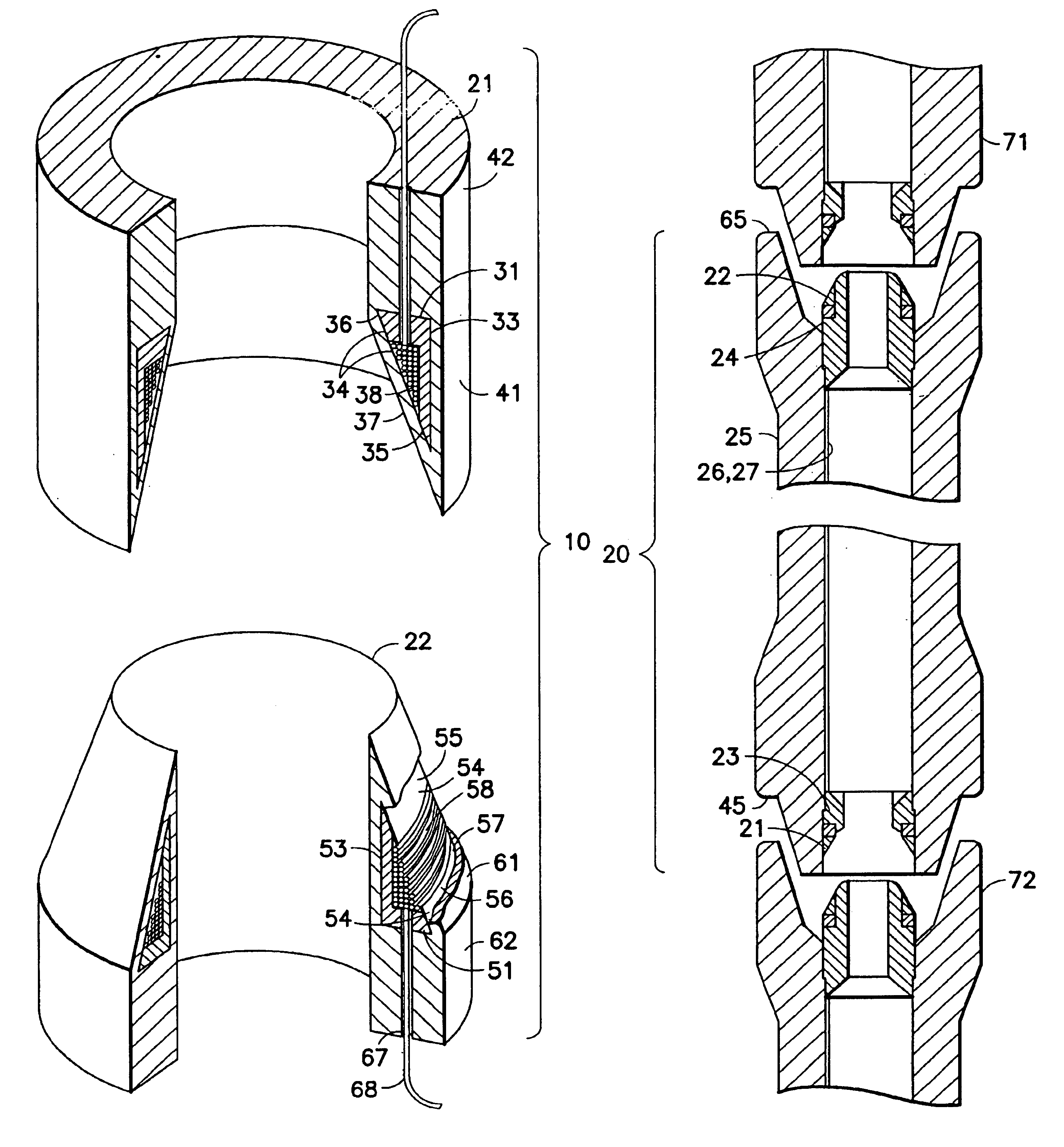
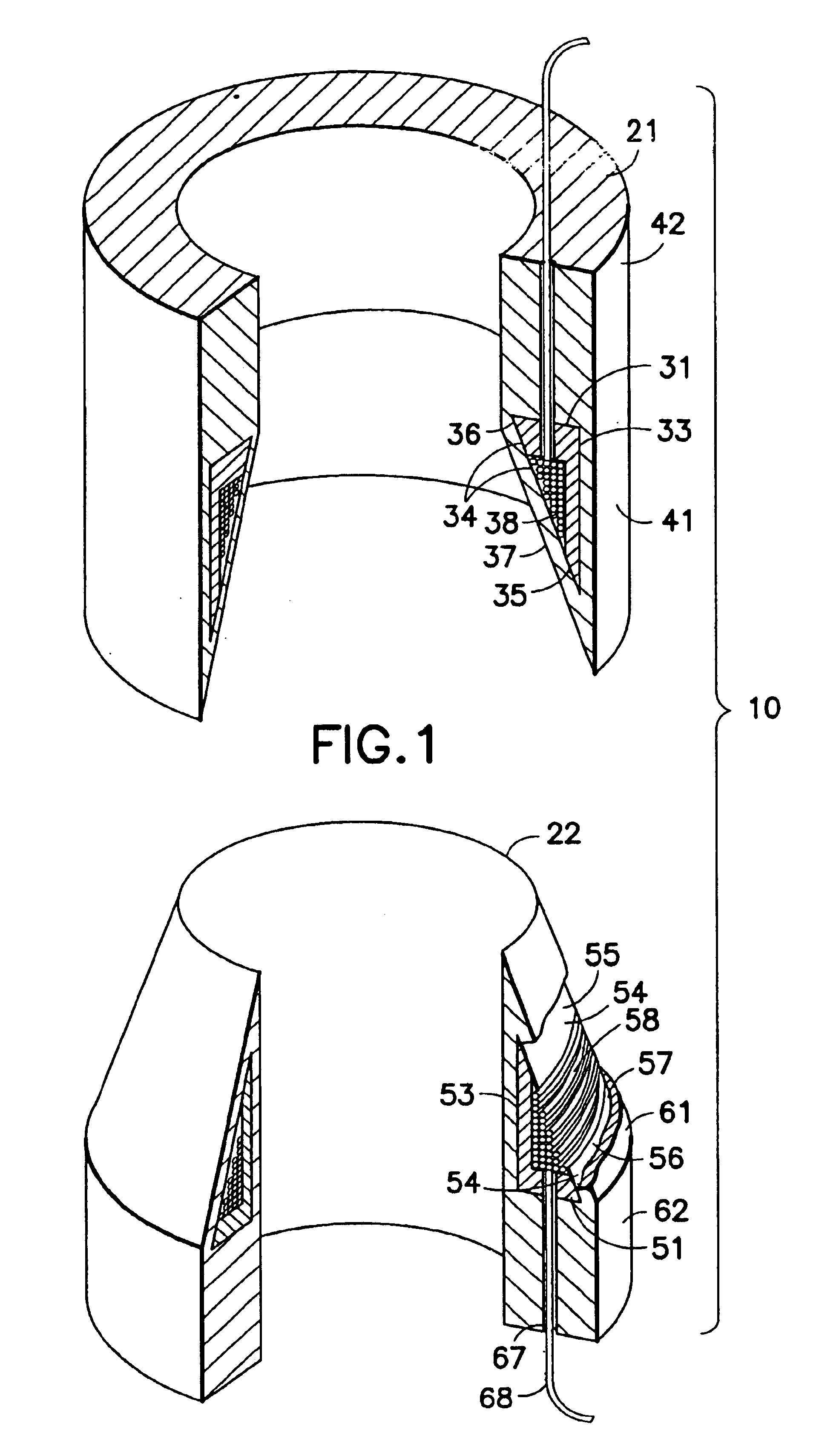
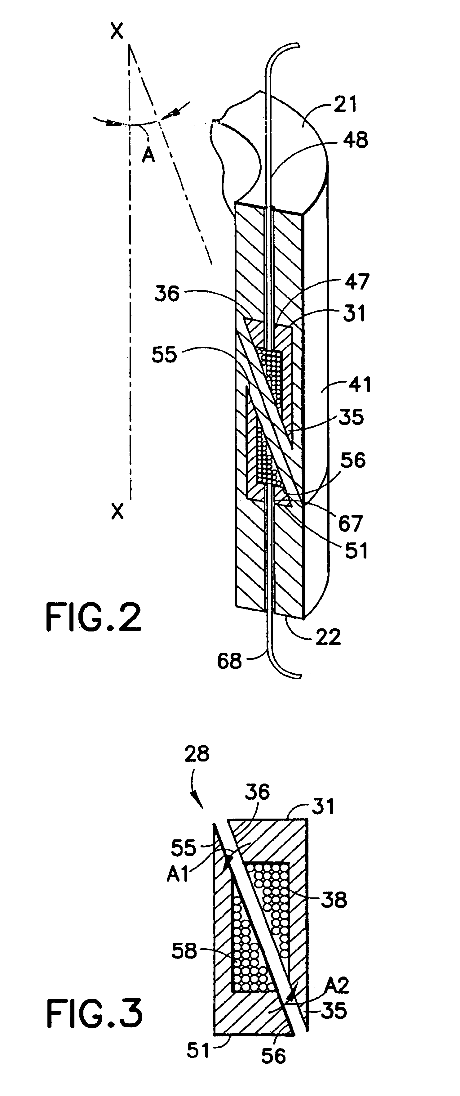
FIG. 1 is a partially cut away perspective view of a first (flux-loop) embodiment of an inductive coupler according to the present invention. FIG. 1 shows low-loss flux-loop inductive coupler 10 having a first flux-loop inductive coupler element 21 and a second flux-loop inductive coupler element 22. Element 21 includes a ring-like first core 31 having high magnetic permeability. First core 31 is shown enclosed within first protective coating 41 that also defines thick cylindrical first end 42. (In some embodiments the protective coating is omitted.) First core 31 defines a first exterior substantially cylindrical face 33 and a first interior conical-section annular face 34. First interior face 34 defines a first interior conical-section annular larger-diameter face 35 (herein below referred to as “first larger-diameter face”), a first interior conical-section annular smaller-diameter face 36 (herein below referred to as “first smaller-diameter face”), and an annular first groove 37...

second embodiment

FIG. 9 is a partially cut away perspective view of a second (current-loop) embodiment of an inductive coupler according to the present invention. FIG. 9 shows low-loss current-loop inductive coupler 110 having a first current-loop inductive coupler element 131 including a first high-conductivity, low-permeability layer defining first high-conductivity, low-permeability shaped belt 133, and a second current-loop inductive coupler element 151 including a second high-conductivity, low-permeability layer defining second high-conductivity, low-permeability shaped belt 153. FIG. 10 is an enlarged cross section view of the electromagnetic components of mated elements 131 and 151

A low-loss current-loop inductive coupler according to the second embodiment may be viewed as a pair of transformers connected back to back through the metal of the pipe joint connection.

Referring again to FIG. 9, first current-loop inductive coupler element 131 includes a first coil 142 wound about a first ring-lik...

third embodiment

FIG. 14 is a cross section view of a third embodiment of a low-loss inductive coupler according to the present invention having first and second current-loop inductive coupler elements. In this embodiment, first and second cores and first and second high-conductivity, low-permeability layers are located proximate to the sealing faces of the wired pipe joint.


PUM

PropertyMeasurementUnit
Electrical conductivityaaaaaaaaaa
Diameteraaaaaaaaaa
Shapeaaaaaaaaaa

Abstract

A first flux-loop inductive coupler element electrically couples with a second flux-loop inductive coupler element. The first flux-loop inductive coupler element comprises a first ring-like core having high magnetic permeability and a conical-section annular first face transverse to the plane of the first core. The first face has a first annular groove separating a first conical-section larger-diameter face and a first conical-section smaller-diameter face. A first coil is wound within the annular groove. The first and second cores form a low-reluctance closed magnetic path around the first coil and a second coil of the second flux-loop inductive coupler element.
A first current-loop inductive coupler element electrically couples with a second current-loop inductive coupler element. The first current-loop inductive coupler element has a first high-conductivity, low-permeability shaped belt of a first end of a first pipe joint, a first ring-like core located at the first end, and a first electrically conductive coil wound about the first ring-like core. The first high-conductivity, low-permeability shaped belt partially encloses the first coil. It is shaped to cooperate with the second high-conductivity, low-permeability shaped belt of an adjacent second pipe joint having a second electrically conductive coil and a second high-conductivity, low-permeability shaped belt to create a closed toroidal electrical conducting path. The closed toroidal electrical conducting path encloses the first coil and the second coil when the first and second pipe joints are mated.

Description

TECHNICAL FIELDThe present invention relates to apparatus and methods used in oil well drilling and oil well operations for transmitting measurement data to a surface station from locations in a borehole.BACKGROUND OF THE INVENTIONMeasurement While Drilling (MWD) and Logging While Drilling (LWD) systems derive much of their value from the ability to provide real-time information about conditions near the drill bit. Oil companies use these downhole measurements to make decisions during the drilling process, and sophisticated drilling techniques, such as the GeoSteering system developed by Schlumberger, Ltd. Such techniques rely heavily on instantaneous knowledge of the formation that is being drilled. The industry continues to develop new measurements for MWD / LWD, including imaging type measurements with high data content.These new measurement and control systems require telemetry systems having higher data rates than those currently available. As a result, a number of telemetry tech...

Claims


Application Information

Patent Timeline
IPC IPC(8): E21B17/02F16L25/00F16L15/08F16L25/01F16L15/00E21B47/12
CPCE21B17/028E21B47/122F16L25/01F16L15/08Y10S439/95E21B47/13E21B17/0283
Inventor BOYLE, BRUCE W.MADHAVAN, RAGHUJUNDT, JACQUES
Owner SCHLUMBERGER TECH CORP
Why Eureka
Try Eureka