Reflective liquid crystal display

a liquid crystal display and reflection technology, applied in the field of frontlight type reflective liquid crystal displays, can solve the problems of increasing the luminance variations of large-sized screens and color screens, and achieve the effect of suppressing luminance changes and excellent visual recognition (or visibility)

Inactive Publication Date: 2005-03-15
NITTO DENKO CORP
View PDF10 Cites 45 Cited by
  • Summary
  • Abstract
  • Description
  • Claims
  • Application Information

AI Technical Summary

Benefits of technology

This invention intends to provide a front-light type reflective liquid crystal display (LCD) which suppresses changes in t

Problems solved by technology

Probably, this disadvantageously increases variations in

Method used


Image

  • Reflective liquid crystal display
  • Reflective liquid crystal display
  • Reflective liquid crystal display

Examples


embodiments

Embodiment 1

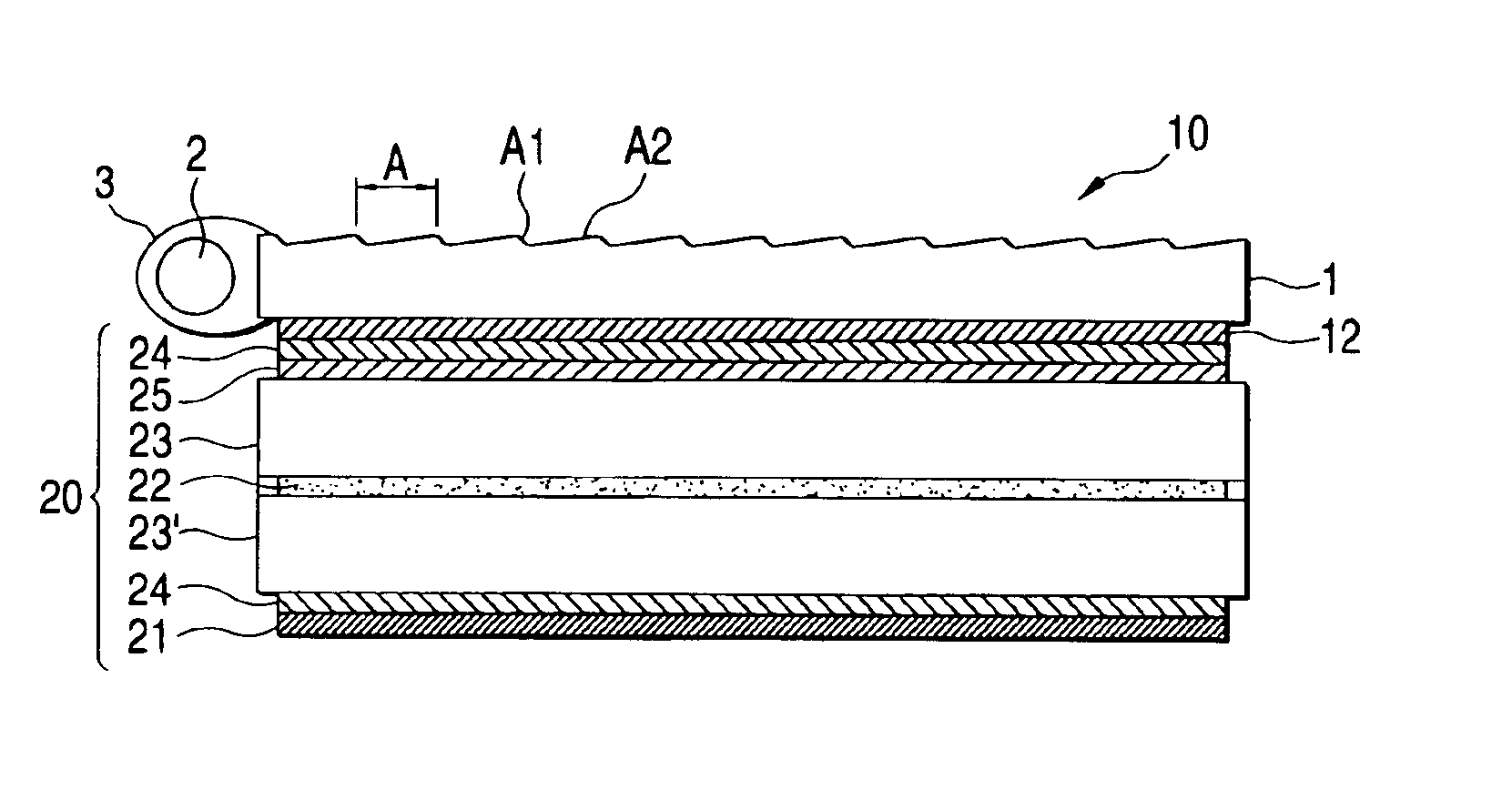
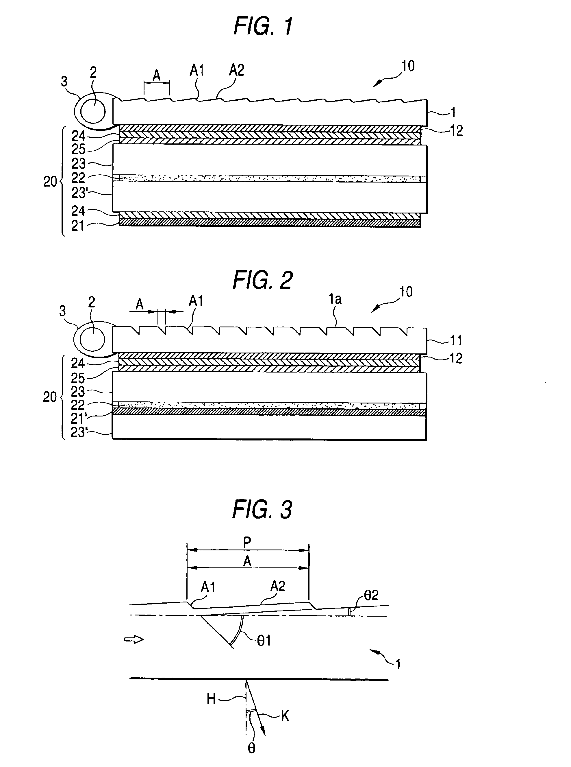
The one side surface of a polymethylmethacrylate machined in a prescribed shape (refractive index of 1.50) was cut using a diamond bite to provide a light pipe having a light emitting means. The light pipe has a width of 60 mm, depth of 80 mm, a thickness on an incident side of 1.2 mm, and an opposite end thickness of 0.6 mm. The light pipe has upper and lower flat surfaces. On the upper flat surface, successive grooves each of which is triangular in section are formed with pitches of 240 μm. The grooves each has a vertical angle has an optical path converting plane with an apex angle of 70° in parallel to the incident side and a tilt angle of 42.5°. The flat plane resides between the grooves (FIG. 2). The optical path converting plane has a width of 10-16 μm projected on the lower surface, which increases as it leaves from the incident side. The ratio in the projected area of the flat plane to optical path converting plane for the lower surface is 15 / 1 or more. Incident...


PUM


Abstract

A reflective liquid crystal display (LCD) is constituted by a light pipe which emits incident light from an incident side from the other surface of its upper and lower surfaces through light emitting means formed on the one of them, a plane light source device with a light source arranged on one or more sides of the light pipe, and a liquid crystal display (LCD) panel having a reflective layer. The light emitting side of the plane light source device and the visual recognition side of the LCD panel are bonded to each other through an adhesive layer having a refractive index lower than that of the light pipe.

Description

BACKGROUND OF THE INVENTION1. Field of the InventionThis invention relates to a front-light type reflective liquid crystal display (LCD) which is excellent in the using efficiency of light, bright and easy to see.The present application is based on Japanese Patent Application No. 2000-203944, which is incorporated herein by reference.2. Description of the Related ArtA front-light type reflective LCD is previously known which is provided with a plane light source device of a sidelight type light pipe, which permits visual recognition in the darkness, on a visual recognition side (Unexamined Japanese Patent Publications Nos. Hei. 11-250715 and 11-306829) However, only arrangement of the plane light source device on the side of visual recognition increases interface reflection owing to existence of an air interface and the reflected light overlaps a displayed image on a liquid crystal display (LCD) panel to cause white blooming and reduction in the contrast. In order to obviate such in...

Claims


Application Information

Patent Timeline
IPC IPC(8): F21V8/00G02F1/1335G02F1/13G02B6/00G02F1/13357G09F9/00
CPCG02B6/0038G02F2001/133616G02B6/0051G02F1/133616G02F1/1335
Inventor YANO, SHUUJIUMEMOTO, SEIJI
Owner NITTO DENKO CORP
Why Eureka
Try Eureka