Miniature gas turbine engine with unitary rotor shaft for power generation

a gas turbine engine and unitary technology, applied in the direction of liquid fuel engines, magnetic circuit rotating parts, magnetic circuit shapes/forms/construction, etc., can solve the problems of increasing the complexity of the assembly process, increasing and increasing the difficulty of scaling the scaling effect of miniature devices. achieve the effect of eliminating the cost of post-process assembly and high quality

Inactive Publication Date: 2005-03-15
THE BOARD OF TRUSTEES OF THE LELAND STANFORD JUNIOR UNIV +1
View PDF18 Cites 29 Cited by
  • Summary
  • Abstract
  • Description
  • Claims
  • Application Information

AI Technical Summary

Benefits of technology

Accordingly, it is a primary goal of the present invention to provide a new, useful, and reliable miniature gas turbine engine for power generation. This goal is achieved with a high quality and high performance unitary rotor shaft that combines and integrates turbine, compressor, and shaft in one piece. Preferably, the Mold SDM fabrication technique is utilized to make the unitary rotor shaft in one monolithic, three-dimensional part out of ceramics such as silicon nitride, an extremely strong material. The turbine and compressor are positioned back to back on the shaft in an overhung configuration, allowing the front bearings to be located in the cold zone of the engine.
Integrated with a permanent magnet in the unitary rotor shaft, the miniature gas turbine engine can generate electric power of 1 kW or les

Problems solved by technology

Furthermore, Bescoby does not address whether the unitary rotating assembly is suitable for generating power in miniature applications.
Due to design and shape complexities, individual components are manufactured separately and assembled by using a various kind of joining techniques.
For miniature applications, such conventional assembly process becomes more challenging as the size of the components is scaled down.
As one skilled in the art would appreciate, since the physics and mechanics influencing the design of the components of a miniature device do change with

Method used


Image

  • Miniature gas turbine engine with unitary rotor shaft for power generation
  • Miniature gas turbine engine with unitary rotor shaft for power generation
  • Miniature gas turbine engine with unitary rotor shaft for power generation

Examples


Embodiment Construction

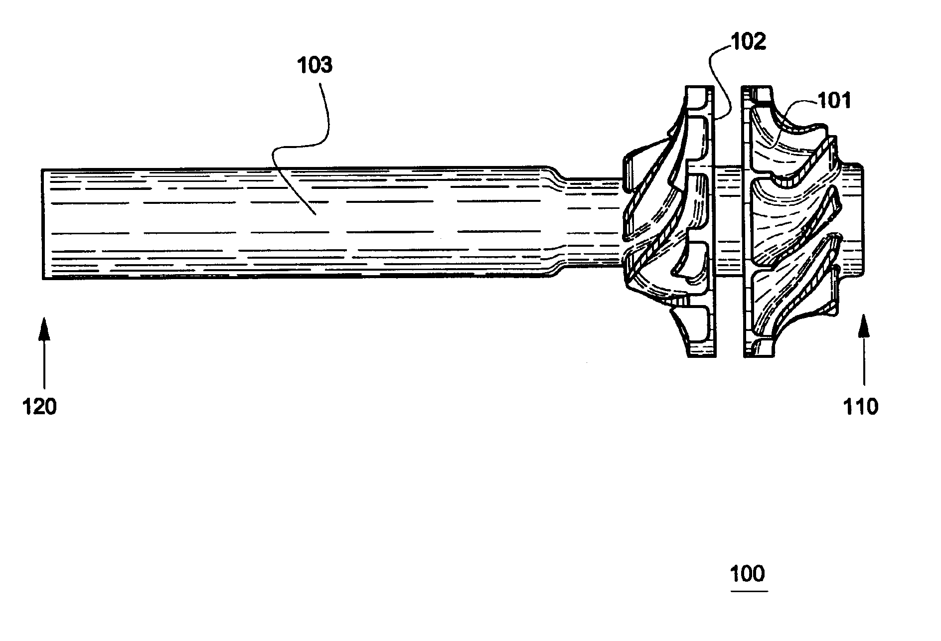
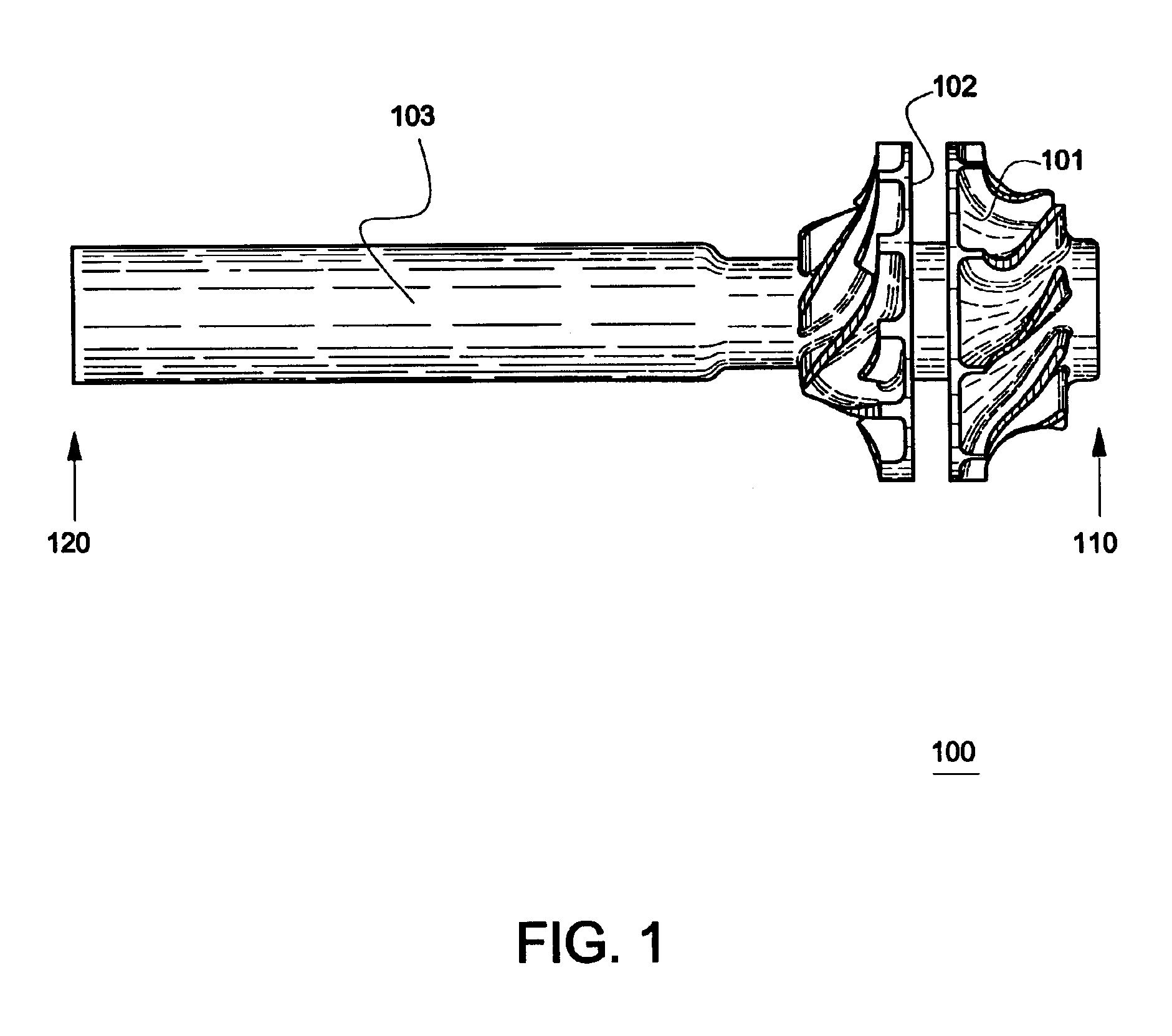
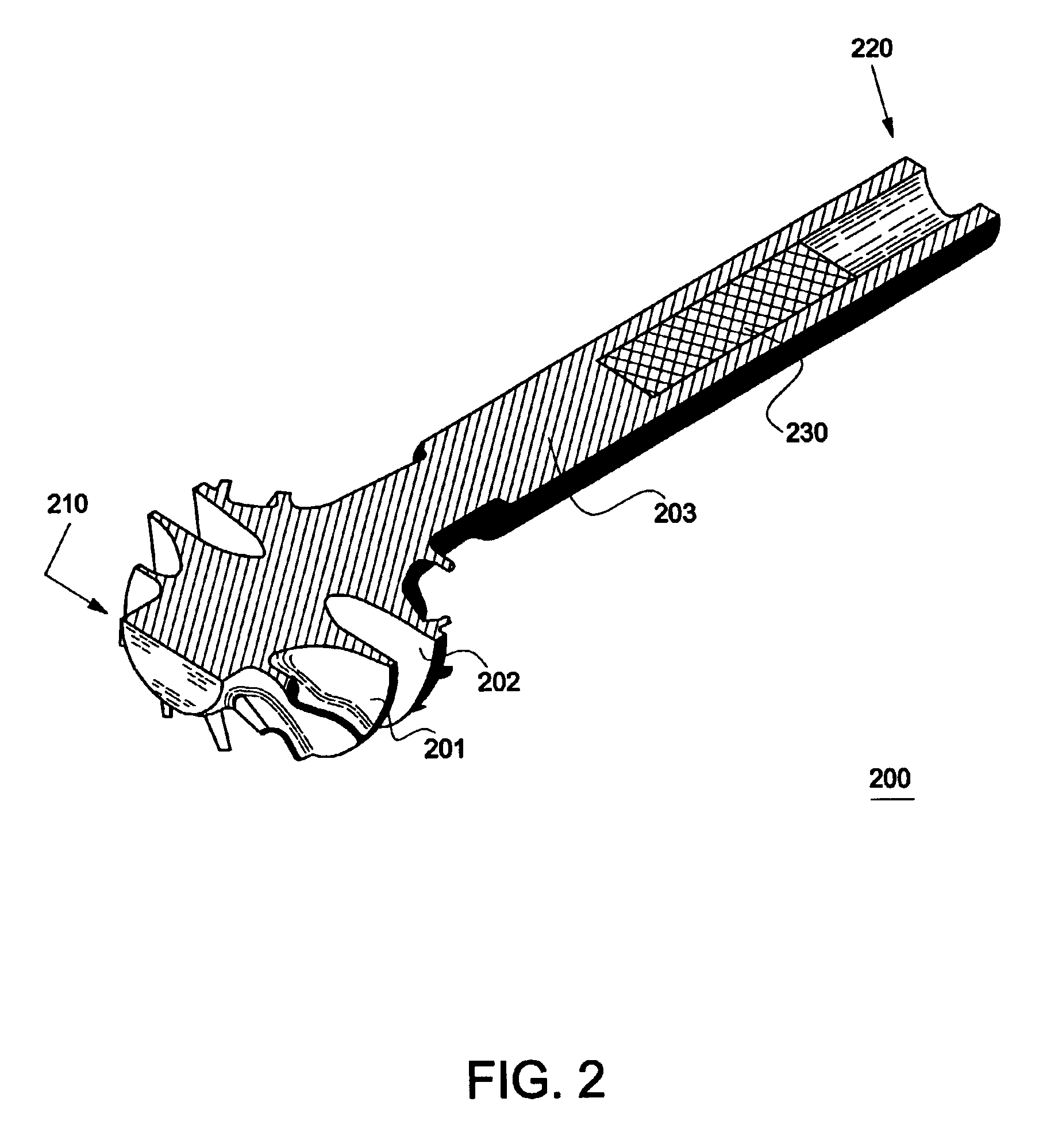
This invention presents a new and inventive miniature gas turbine engine for power generation with a unitary rotor shaft where turbine, compressor and shaft are made in one piece. Utilizing novel fabrication techniques for very small, intricate, and three-dimensionally complicated components, this inventive design advantageously eliminates the post process shaft assembly, enables the manufacturing of a high-quality and high-performance unitary rotor shaft, thereby provides a viable and reliable miniature gas turbine engine for power generation. The size of miniature gas turbine engine is about 100 mm or less in axial length and it generates electric power of about 1 kW or less, e.g., about 100 W. Because of its small size and lightweight, the miniature gas turbine engine is particularly suitable for a power supply device in mobile applications.

There is an ongoing effort in the art to develop micro scale, lightweight power generator for portable power sources, autonomous robots, and ...


PUM

PropertyMeasurementUnit
Lengthaaaaaaaaaa
Lengthaaaaaaaaaa
Lengthaaaaaaaaaa

Abstract

The present invention provides a miniature gas turbine engine for power generation. The engine has a highly integrated unitary rotor shaft where turbine, compressor and shaft are made in one piece in one fabrication process. The turbine and compressor are positioned back to back on the shaft in an overhung configuration, allowing the front bearings to be located in the cold zone of the engine. Preferably, the Mold SDM fabrication technique is utilized to make the unitary rotor shaft in one monolithic part out of ceramics such as silicon nitride, eliminating the need for post process assembly while strengthening the integrity, reliability, and performance of the unitary rotor shaft. Integrated with a permanent magnet in the unitary rotor shaft, the miniature gas turbine engine can generate electric power of 1 kW or less. Additionally, the axial length of the miniature gas turbine engine is about 100 mm or less. The miniature gas turbine engine according to the present invention is therefore particularly useful for powering lightweight, self-sustaining mobile devices such as unmanned vehicles and-autonomous robots.

Description

BACKGROUND OF THE INVENTION1. Field of the InventionThe present invention relates generally to miniaturized turbomachines, and, more particularly, to a miniature gas turbine engine for power generation with a unitary rotor shaft where turbine, compressor, rotor shaft, and power generator are integrated in one piece.2. Description of the Related ArtThe fundamental components of a gas turbine engine for power generation include a combustor, a turbine, a compressor, a rotor shaft, and an alternator, which is on the extension of the rotor shaft and which converts mechanical energy into usable electric power. The turbine and compressor reside in a high temperature (hot) zone of the engine while the rotor shaft, carrying the turbine and compressor, extends from the hot zone to a low temperature (cold) zone. In known gas turbine engines, the turbine, compressor, and rotor shaft are usually joined or assembled and not fabricated as one piece. Furthermore, the rotor shaft may be made of two ...

Claims


Application Information

Patent Timeline
IPC IPC(8): F01D11/08F01D5/02F02C3/00F01D21/00F01D11/22F01D21/04F01D5/04F01D25/16F01D5/28F02C3/05H02K1/27H02K7/18
CPCF01D5/048F01D5/284F01D25/16F02C3/05H02K7/1823H02K1/2726F05D2250/82F05D2300/2283F05D2270/60Y10S415/915F05D2220/768B33Y80/00B33Y70/00
Inventor FABIAN, TIBORHOLMAN, FRANKKANG, SANGKYUNLIU, HAO-CHIHMATSUNAGA, MINORUPRINZ, FRITZ B.TSURU, HIDEAKI
Owner THE BOARD OF TRUSTEES OF THE LELAND STANFORD JUNIOR UNIV
Why Eureka
Try Eureka