System for phase inversion ultrasonic imaging

a phase inversion ultrasonic imaging and phase inversion technology, applied in the field of ultrasonic imaging, can solve the problems of ineffective averaging alone in locating images of interest between tissues with similar densities, exacerbated interpretation difficulties, and difficult to determine the exact location and proper interpretation of received signals

Inactive Publication Date: 2005-03-15
SHENZHEN MINDRAY BIO MEDICAL ELECTRONICS CO LTD
View PDF1 Cites 50 Cited by
  • Summary
  • Abstract
  • Description
  • Claims
  • Application Information

AI Technical Summary

Benefits of technology

The present invention is based on the observation that many types of media scatter sound in a non-linear manner. With an ultrasonic imaging system based on linear-scattering media, the return signal is a time-shifted, amplitude-scaled version of the incident signal. Non-linear scattering media produce signals that cannot be produced by simple time-shifts, scaling, or summation of the signal incident to a scattering site. The phase of an ultrasound wave reflected from the boundary of a non-linear medium is altered in a manner that depends on the phase of the incident sound pulse. For example, consider the special case of two ultrasound pulses (k=2), where the phase difference between the two transmitted sound pulses differ by 360⁢°k=360⁢°2

Problems solved by technology

While ultrasonic procedures have a distinct number of advantages over other types of diagnostic techniques, prior art methods and systems have noise problems that make it difficult to determine the exact location and proper interpretation of the received signal.
Various forms of averaging techniques have been employed to reduce the noise, but averaging alone is ineffective in locating images of interest between tissues with similar densities.
These interpretation difficulties are exacerbated by the fact that many tissues in the human body have similar densities.

Method used


Image

  • System for phase inversion ultrasonic imaging
  • System for phase inversion ultrasonic imaging
  • System for phase inversion ultrasonic imaging

Examples


Embodiment Construction

The present invention relates to the field of ultrasound imaging. This invention utilizes broad beam technology (B2 Technology™) to perform image extraction of the non-linear elements of media under investigation. These media will hereinafter be referred to as media of interest. Broad beam technology defines an area under investigation at a given point in time, which is in contrast with a system utilizing a focused beam.

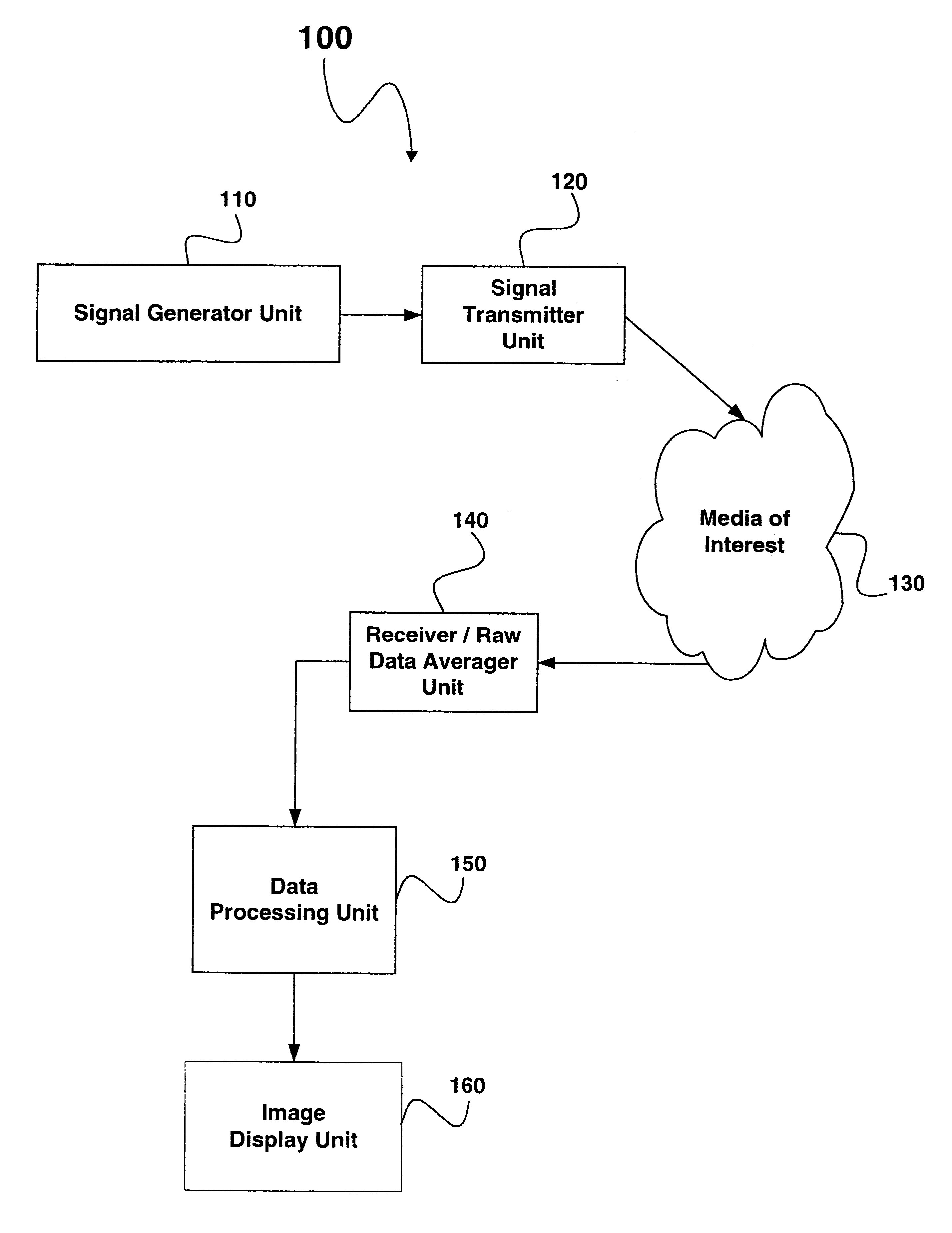
FIG. 1 is a block diagram of an embodiment of an ultrasound imaging system using the present invention. Imaging system 100 includes at least one signal generator unit 110, at least one signal transmitter unit 120, media of interest 130 to be imaged, at least one receiver and raw data averager unit 140 to capture signals received from the media of interest 130, and a data processing unit 150 for taking the averaged received signals and producing an area of image formation on an image display unit 160.

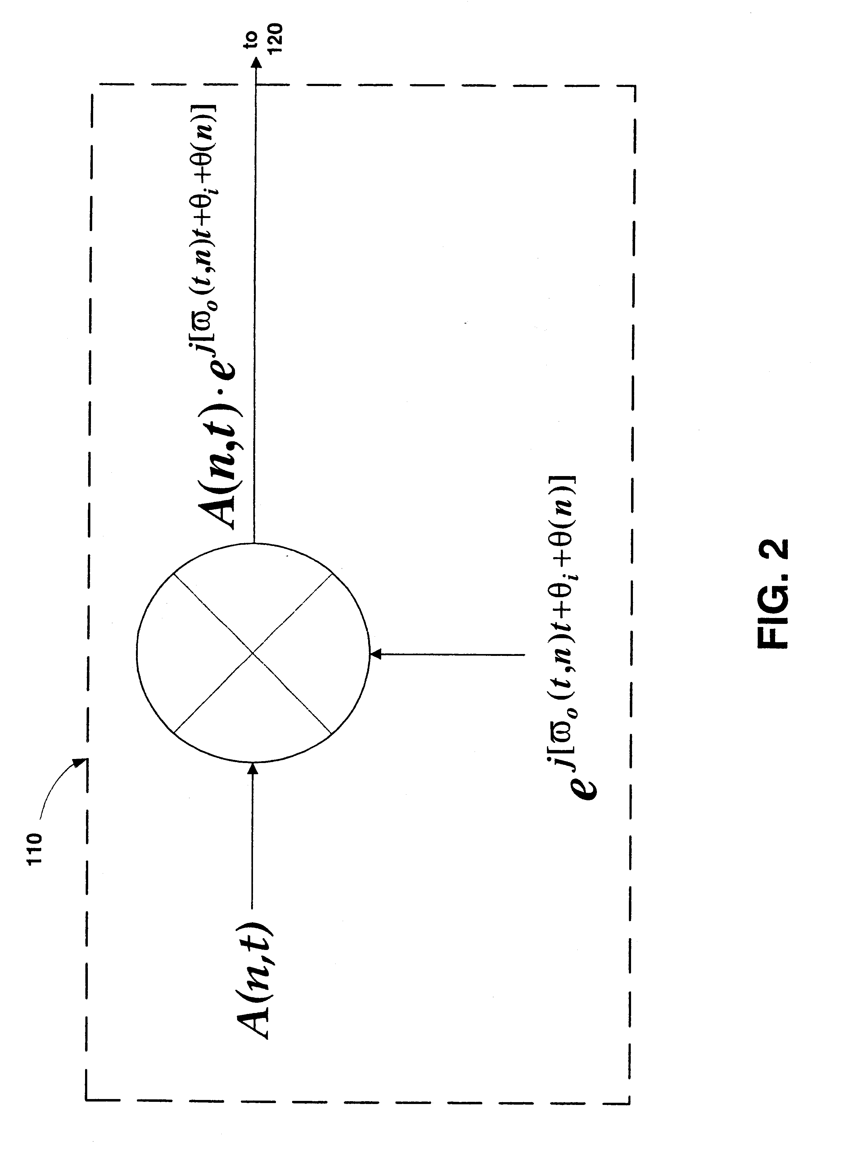
A signal generator unit 110 drives circuitry for a signal transmitte...


PUM

PropertyMeasurementUnit
phaseaaaaaaaaaa
out-of-phaseaaaaaaaaaa
ultrasound imagingaaaaaaaaaa

Abstract

A system and method for ultrasonic imaging utilizing multiple sets of transmit pulses differing in amplitude, frequency, phase, and/or pulse width. One embodiment has phase differences between the k transmit signal as 360k
degrees providing for constructive interference of the kth order harmonic pulse, while an amplitude modulation of each transmit profile is constant between sets. These sets of pulses are transmitted into media of interest and received echoes from these pulses are combined to form an averaged signal. The averaged pulses represent the net common mode signal received from each of the transmit sets. This combined signal set is used to reconstruct an ultrasound image based on broad beam reconstruction methodology.

Description

CROSS-REFERENCE TO RELATED APPLICATIONSNot ApplicableBACKGROUND OF THE INVENTION1. Field of the InventionThe present invention relates to ultrasound imaging, and more particularly, to a method and apparatus for improving and enhancing ultrasound images.2. Description of the Background ArtUltrasonic imaging is frequently used for a variety of diagnostic procedures due to its non-invasive nature, low cost, and fast response time. These qualities are especially true in medical fields where the added benefit is reducing or eliminating a patient's exposure to radiation. Typically, ultrasound imaging is accomplished by 1) generating and directing an ultrasonic beam into media under investigation; and 2) observing any resulting waves that are reflected back from dissimilar tissues and tissue boundaries within that area. The resulting waves are received as signals. These received signals are then post-processed and imaged on a screen by plotting a spot whose intensity is proportional to the...

Claims


Application Information

Patent Timeline
Patent Type & Authority Patents(United States)
IPC IPC(8): G01S15/89G01S15/00G01S7/52A61B8/00G01N29/44
CPCG01S7/52038G01S15/8963G01S15/8959G01S7/52077G01S7/52026G01S15/104A61B8/00A61B5/7257A61B5/02A61B8/485A61B8/488A61B8/5223A61B8/5238A61B8/5207
Inventor MCLAUGHLIN, GLENJI, TING-LAN
Owner SHENZHEN MINDRAY BIO MEDICAL ELECTRONICS CO LTD
Why Eureka
Try Eureka