
System and method for current-enhanced stress-migration testing of interconnect

a stress-migration failure and interconnect technology, applied in the field of interconnect technology in integrated circuit fabrication, can solve the problems of increasing the stress-migration failure rate of the interconnect test structure, etc., and achieve the effect of reducing the time to stress-migration failur

Inactive Publication Date: 2005-03-15
ADVANCED MICRO DEVICES INC
View PDF3 Cites 34 Cited by
  • Summary
  • Abstract
  • Description
  • Claims
  • Application Information

AI Technical Summary

Benefits of technology

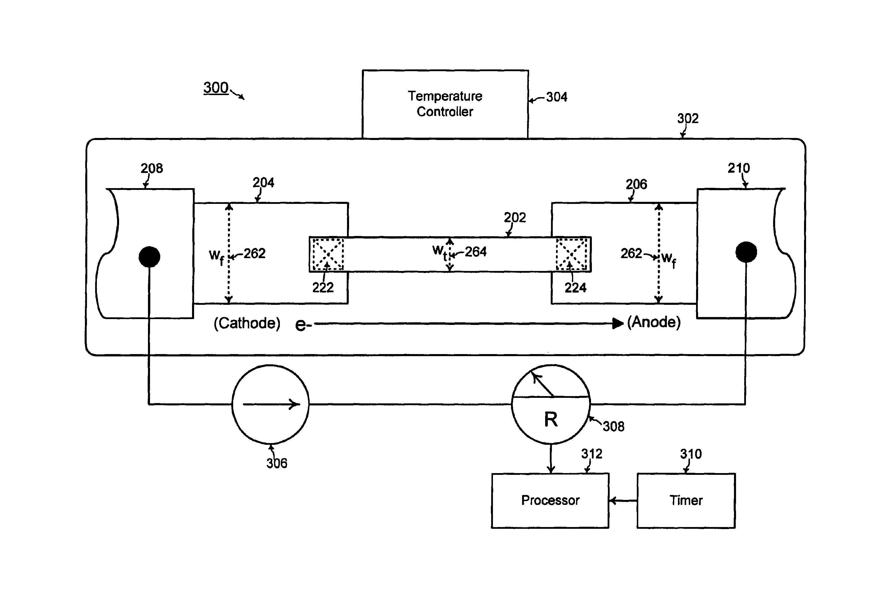
Accordingly, in a general aspect of the present invention, a system and method of testing for stress-migration failure of interconnect reduces the time to stress-migration failure of an interconnect test structure by continuously conducting a critical current level through the interconnect test structure that is continuously heated.
In this manner, with the critical current level constantly flowing through the interconnect test structure that is continuously heated, the interconnect test structure exhibits a shorter stress-migration life-time. A higher current level flowing through the interconnect test structure increases the rate of stress-migration failure of the interconnect test structure. The critical current level is the maximum possible current level flowing through the interconnect test structure before electromigration failure instead of stress-migration failure is exhibited by the interconnect test structure. Thus, the critical current level flowing through the interconnect test structure increases the rate of stress-migration failure of the interconnect test structure as much as possible for stress-migration detection.

Problems solved by technology

A higher current level flowing through the interconnect test structure increases the rate of stress-migration failure of the interconnect test structure.
Thus, the critical current level flowing through the interconnect test structure increases the rate of stress-migration failure of the interconnect test structure as much as possible for stress-migration detection.

Method used


Image

  • System and method for current-enhanced stress-migration testing of interconnect
  • System and method for current-enhanced stress-migration testing of interconnect
  • System and method for current-enhanced stress-migration testing of interconnect

Examples


Embodiment Construction

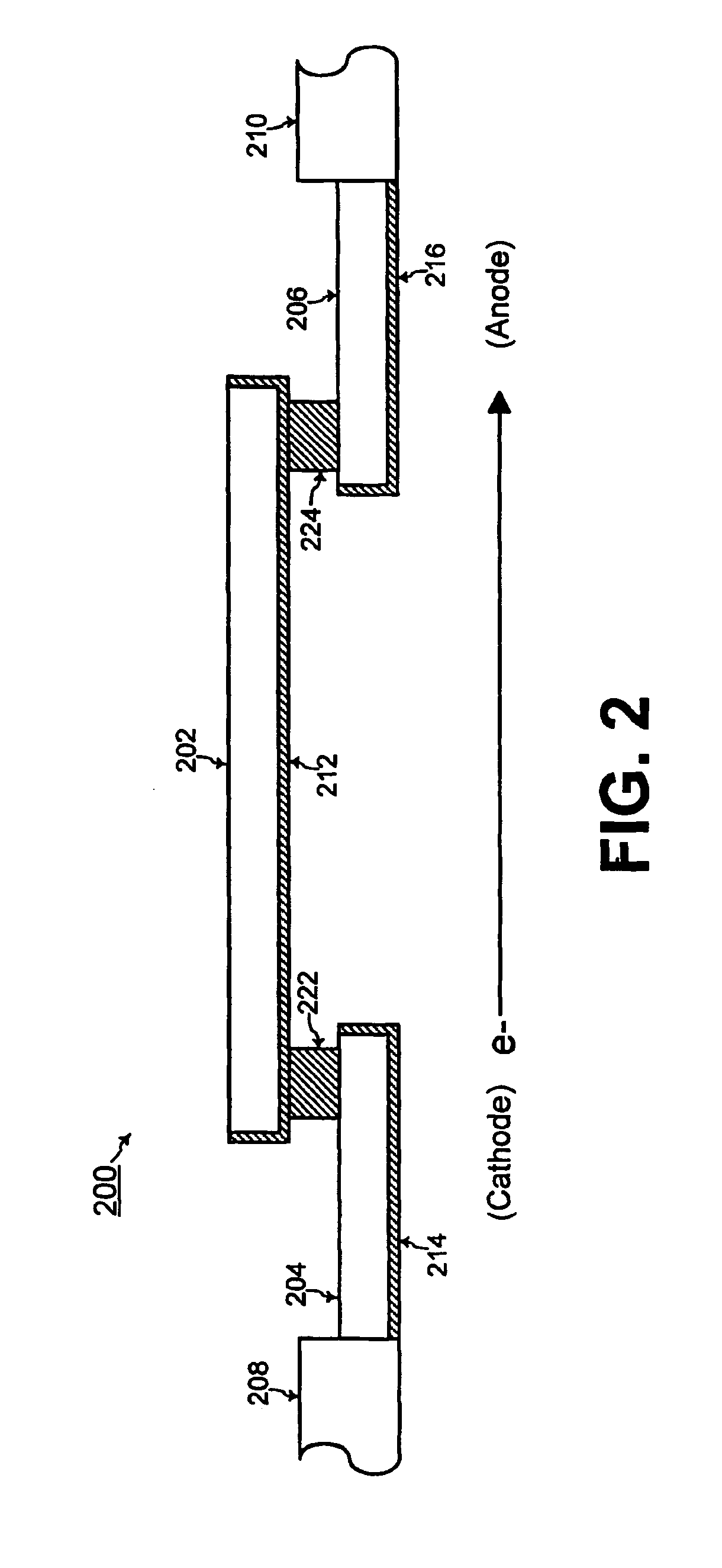
FIG. 2 shows an interconnect test structure 200 including a test line 202, a first feeder line 204, and a second feeder line 206, according to an embodiment of the present invention. The test line 202, the first feeder line 204, and the second feeder line 206 are comprised of copper in one embodiment of the present invention. In that case, the test line 202, the first feeder line 204, and the second feeder line 206 are each surrounded by a respective diffusion barrier layer material 212, 214, and 216. The first feeder line 204 is coupled to a first test pad 208, and the second feeder line 206 is coupled to a second test pad 210.

The test line 202 is coupled to the first feeder line 204 by a first no-flux via structure 222 at a first end of the test line 202, and the test line 202 is coupled to the second feeder line 206 by a second no-flux via structure 224 at a second end of the test line 202. The first and second no-flux via structures 222 and 224 are comprised of tungsten accordin...


PUM


Abstract

For testing for stress-migration failure of interconnect, an interconnect test structure is formed with a first feeder line coupled to a test line by a first no-flux structure, and with a second feeder line coupled to the test line by a second no-flux structure. A respective width of ea ch of the first and second feeder lines is greater than a width of the test line. A resistance meter and a timer measure a stress-migration life-time of the interconnect test structure with a current being continuously conducted through the interconnect test structure that is continuously heated to a predetermined temperature.

Description

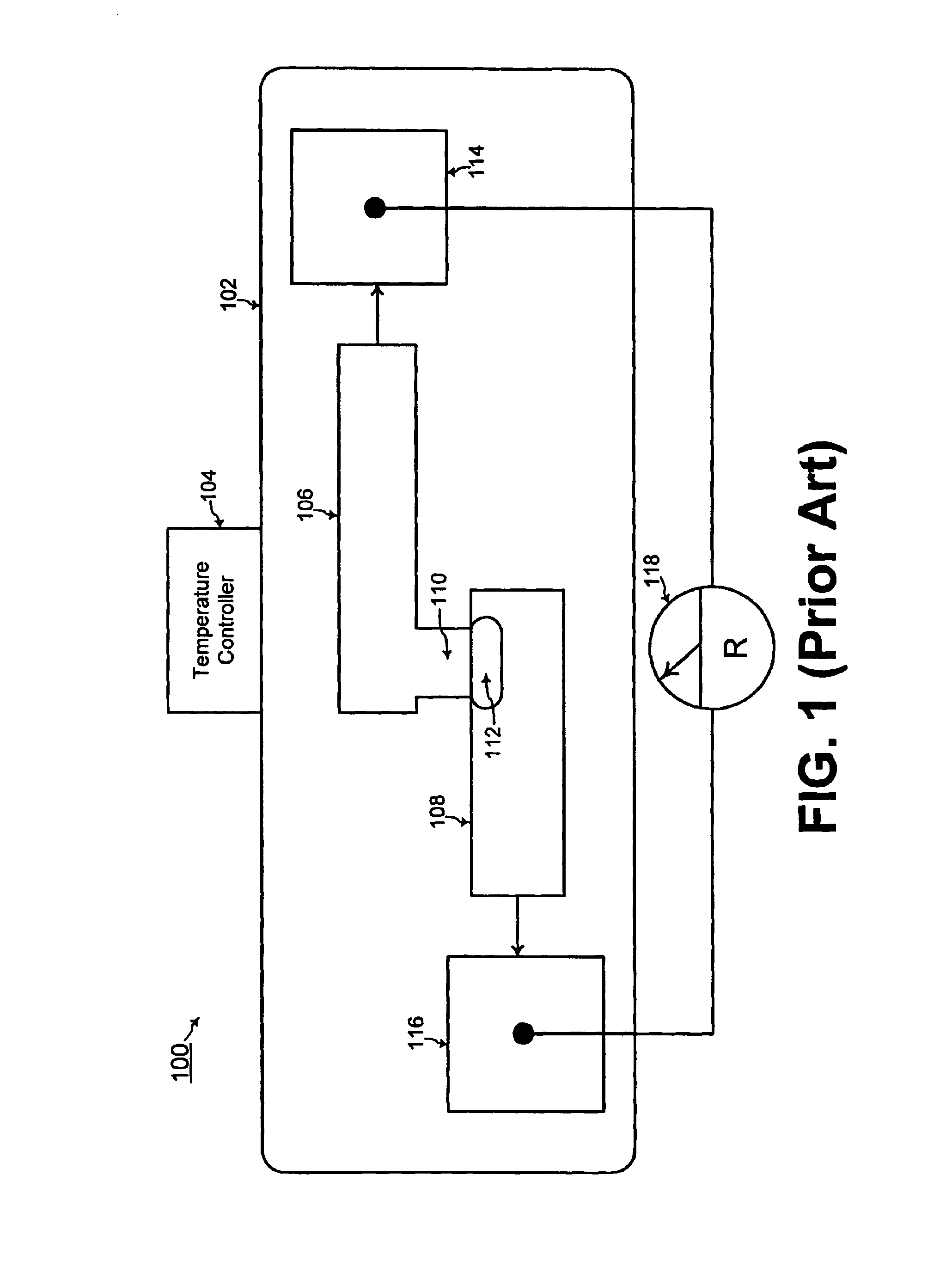
TECHNICAL FIELDThe present invention relates generally to interconnect technology in integrated circuit fabrication, and more particularly, to a system and method of testing for stress-migration failure of interconnect with current continuously conducted through the interconnect for accelerated testing.BACKGROUND OF THE INVENTIONReferring to FIG. 1, a system 100 of the prior art for testing interconnect for stress-migration failure includes a heating chamber 102 with a temperature controller 104. The interconnect structure includes a test line 106 and a feeder line 108. The test line 106 is coupled to the feeder line 108 by a via structure 110 that is part of the dual damascene structure of the test line 106. The temperature controller 104 is used for controlling the temperature within the heating chamber 102, and such a heating chamber is known to one of ordinary skill in the art of integrated circuit fabrication.When the interconnect structure including the test line 106, the feed...

Claims


Application Information

Patent Timeline
Patent Type & Authority Patents(United States)
IPC IPC(8): H01L23/544G01R31/28
CPCH01L22/34G01R31/2858
Inventor HAU-RIEGE, CHRISTINEMARATHE, AMIT P.
Owner ADVANCED MICRO DEVICES INC
Learn More