

Organic electroluminescence device and phenylenediamine derivative
a technology of electroluminescence device and phenylenediamine, which is applied in the direction of luminescnet screen of discharge tube, other domestic articles, natural mineral layered products, etc., can solve the problems of insufficient hole mobility, insufficient driving voltage in the region of high electric current injection, and insufficient lowering of driving voltag
- Summary
- Abstract
- Description
- Claims
- Application Information
AI Technical Summary
Benefits of technology
Problems solved by technology
Method used
Image

Examples
example 1
(Synthesis of 4-Iodotriphenylamine)
[0180]125 g of triphenylamine (produced by Hiroshima Wako & Co., Ltd.) was dissolved in 5 L of ethanol by heating, to which 150 g of mercury oxide was added at 60° C., and then 100 g of iodine was gradually added. Thereafter, the reaction was conducted for 2 hours at a reflux temperature.
[0181]After the reaction, the system was filtered under hot, and the residue was washed with acetone. The filtrate was cooled, and crystals thus deposited were filtered out.
[0182]It was purified by using a column carrying silica gel with toluene as a developing solvent, so as to obtain 52 g of objective substance.
(Synthesis of PD-01)
[0183]10 g of 4,4″-diamino-p-terphenylene (produced by Lancaster Synthesis, Ltd.), 20 g of 1-iodonaphthalene (produced by Hiroshima Wako & Co., Ltd.), 20 g of potassium carbonate, 1 g of copper powder and 100 ml of nitrobenzene were placed in a 300-ml three-neck flask, and were heated under stirring at 200° C. for 48 hours.
[0184]After t...
example 2
(Synthesis of PD-02)
[0188]10 g of 9,10-diaminophenylanthracene (produced by Wakayama Seika Industries, Ltd.), 20 g of 1-iodonaphthalene (produced by Hiroshima Wako & Co., Ltd.), 20 g of potassium carbonate, 1 g of copper powder and 100 ml of nitrobenzene were placed in a 300-ml three-neck flask, and were heated under stirring at 200° C. for 48 hours.
[0189]After the reaction, inorganic matters were filtered out, and the solvents in the mother liquid were distilled off. The residue was purified by using a column carrying silica gel (C-200 produced by Hiroshima Wako & Co., Ltd.) with toluene as a developing solvent, so as to obtain 7.7 g of 9,10-bis(1-naphthylaminophenyl)anthracene.
[0190]5 g thereof, 15 g of 4-iodotriphenylamine, 20 g of potassium carbonate, 1 g of copper powder and 100 ml of nitrobenzene were placed in a 300-ml three-neck flask, and were heated at 200° C. for 60 hours.
[0191]After the reaction, inorganic matters were filtered out, and the solvents in the mother liquid ...
example 3
(Synthesis of PD-03)
[0193]10 g of 4,4′-diaminodiphenylmethane (produced by Hiroshima Wako & Co., Ltd.), 20 g of 1-iodonaphthalene (produced by Hiroshima Wako & Co., Ltd.), 20 g of potassium carbonate, 1 g of copper powder and 100 ml of nitrobenzene were placed in a 300-ml three-neck flask, and were heated under stirring at 200° C. for 48 hours.
[0194]After the reaction, inorganic matters were filtered out, and the solvents in the mother liquid were distilled off. The residue was purified by using a column carrying silica gel (C-200 produced by Hiroshima Wako & Co., Ltd.) with toluene as a developing solvent, so as to obtain 9.6 g of bis(4-(naphthyl-1-yl)aminophenyl)methane.
[0195]5 g thereof, 15 g of 4-iodotriphenylamine, 20 g of potassium carbonate, 1 g of copper powder and 100 ml of nitrobenzene were placed in a 300-ml three-neck flask, and were heated at 200° C. for 60 hours.
[0196]After the reaction, inorganic matters were filtered out, and the solvents in the mother liquid were di...
PUM
| Property | Measurement | Unit |
|---|---|---|
| ionization potential | aaaaa | aaaaa |
| hole mobility | aaaaa | aaaaa |
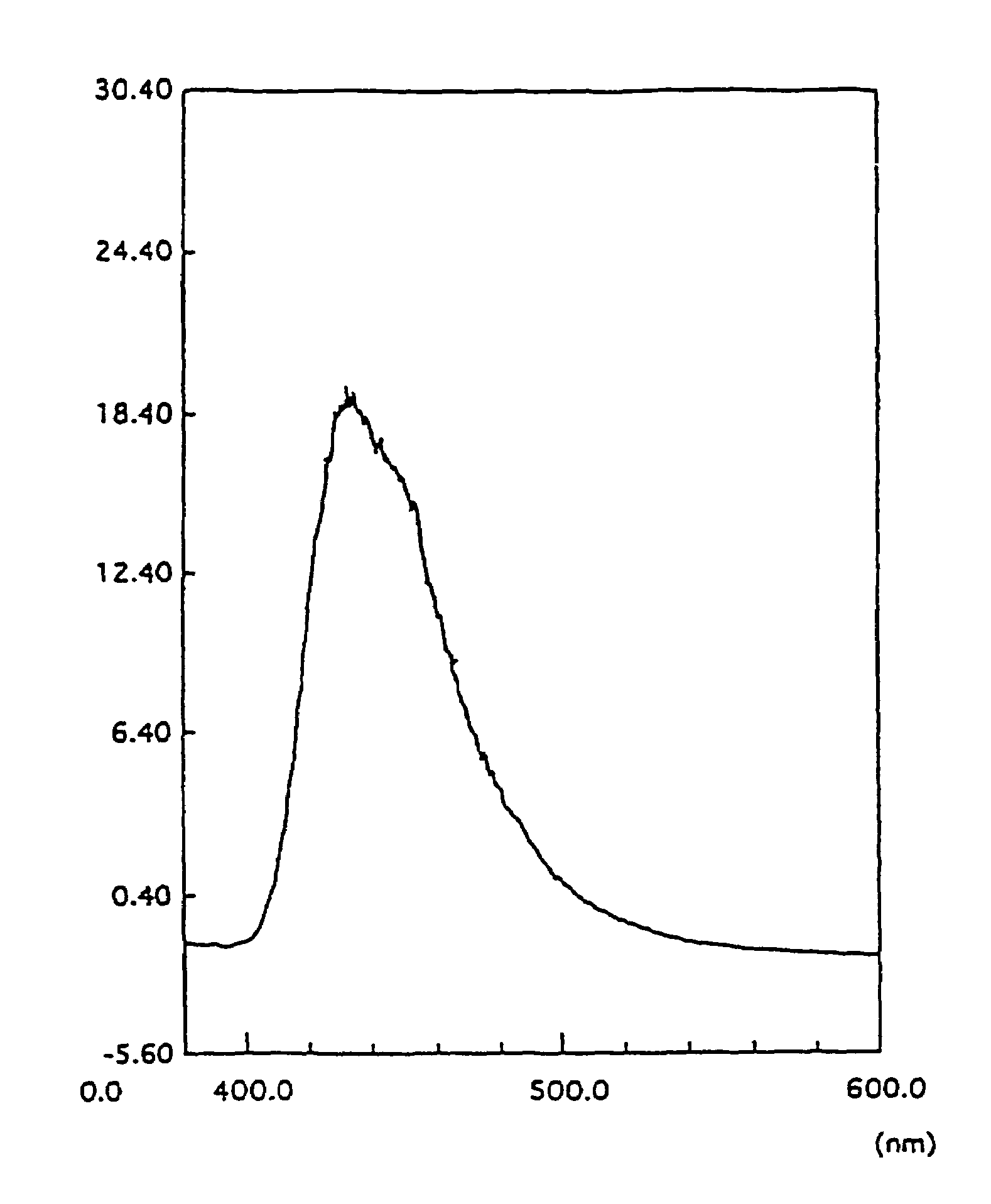
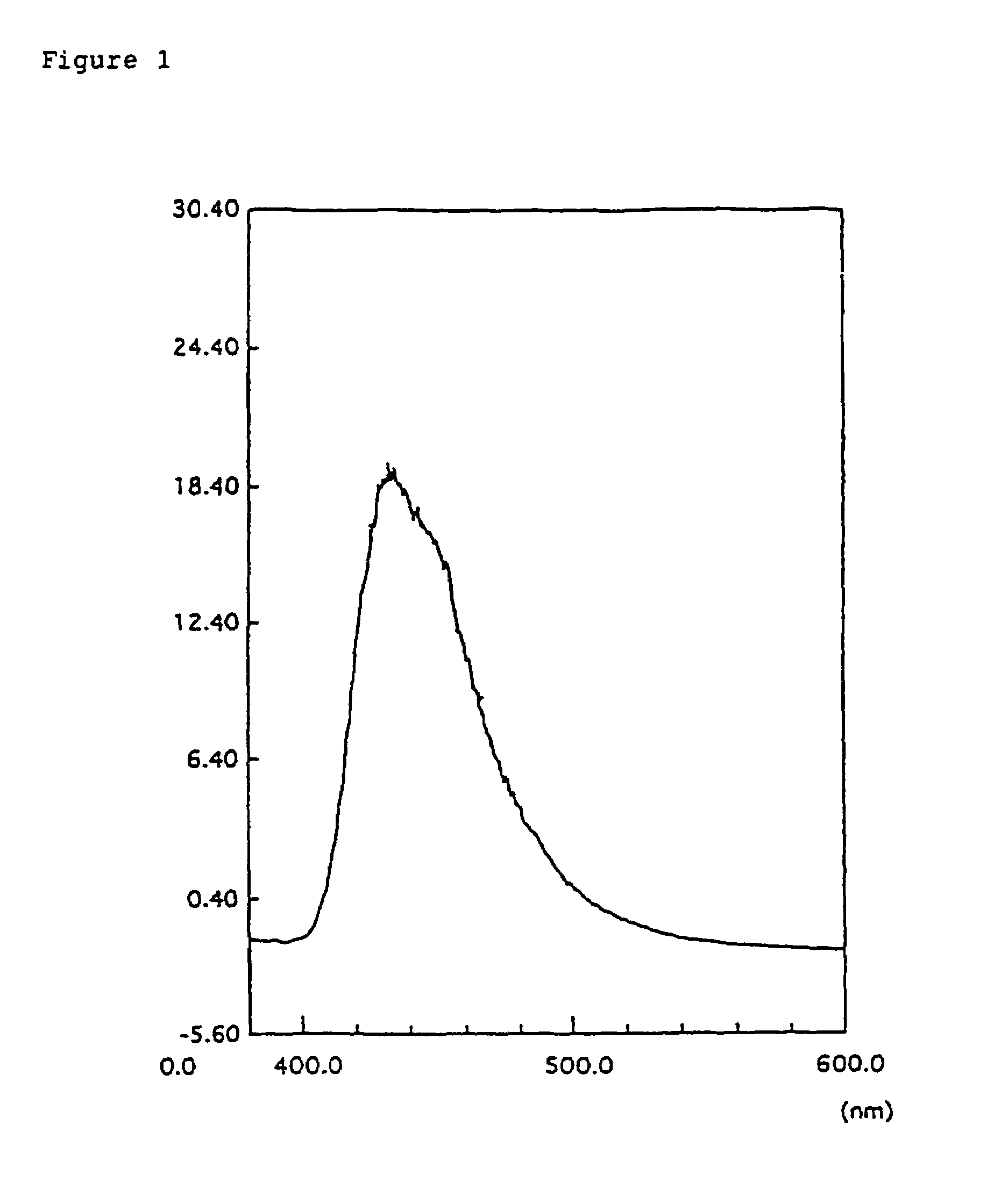
| fluorescent wavelength | aaaaa | aaaaa |
Abstract
Description
Claims
Application Information