Memory mirror system for vehicles

a memory mirror and vehicle technology, applied in the field of vehicle rearview mirror systems, can solve the problems of introducing delay in positioning of reflective elements, serial data communication networks are relatively complicated, strict protocol definitions and hardware requirements, etc., to achieve control the speed at which reflective elements move, avoid overshoot, and low cost

Inactive Publication Date: 2005-03-15
DONNELLY CORP
View PDF59 Cites 49 Cited by
  • Summary
  • Abstract
  • Description
  • Claims
  • Application Information

AI Technical Summary

Benefits of technology

Preferably, the positioning controller is a servo-controller circuit. The use of a servo-controller circuit provides a reliable analog circuit which is capable of responding to the analog signals formatted on the analog interface in order to reliably position the reflective element at its desired final position. Advantageously, the servo-controller circuit can be implemented in an application-specific-integrated-circuit for low-cost, high-volume production. Alternatively, other forms of positioning controllers may be used.
According to another aspect of the invention, a vehicle memory mirror system includes a vehicle mirror assembly and a control module. The vehicle mirror assembly includes a reflective element, a motor for positioning the reflective element upon an axis, a monitor for monitoring the position of the reflective element with respect to the axis, and a mirror-based control operatively connected with the motor and the monitor in order to position the reflective element at a particular position with respect to the axis. The control module is interconnected with the mirror-based control by an interface. The control module includes a processor for providing analog signals on the interface indicative of a desired position of the reflective element with respect to the axis. The processor controls the speed at which the reflective element moves toward a terminal position by formatting signals which each represent an incremental movement of the reflective element with respect to the axis. In this manner, should the processor wish to move the reflective element to a final position at a high rate of speed, the processor formats signals representing the final position of the reflective element or large incremental movement signals. The vehicle-based control will then respond by moving the reflective element at a speed limited only by the hardware of the vehicle mirror assembly. If, however, the control module intends to move the reflective element at

Problems solved by technology

Because mirror-positioning messages would be considered lower priority messages, the serial data communication network may often introduce delays in positioning of the

Method used


Image

  • Memory mirror system for vehicles
  • Memory mirror system for vehicles
  • Memory mirror system for vehicles

Examples


Embodiment Construction

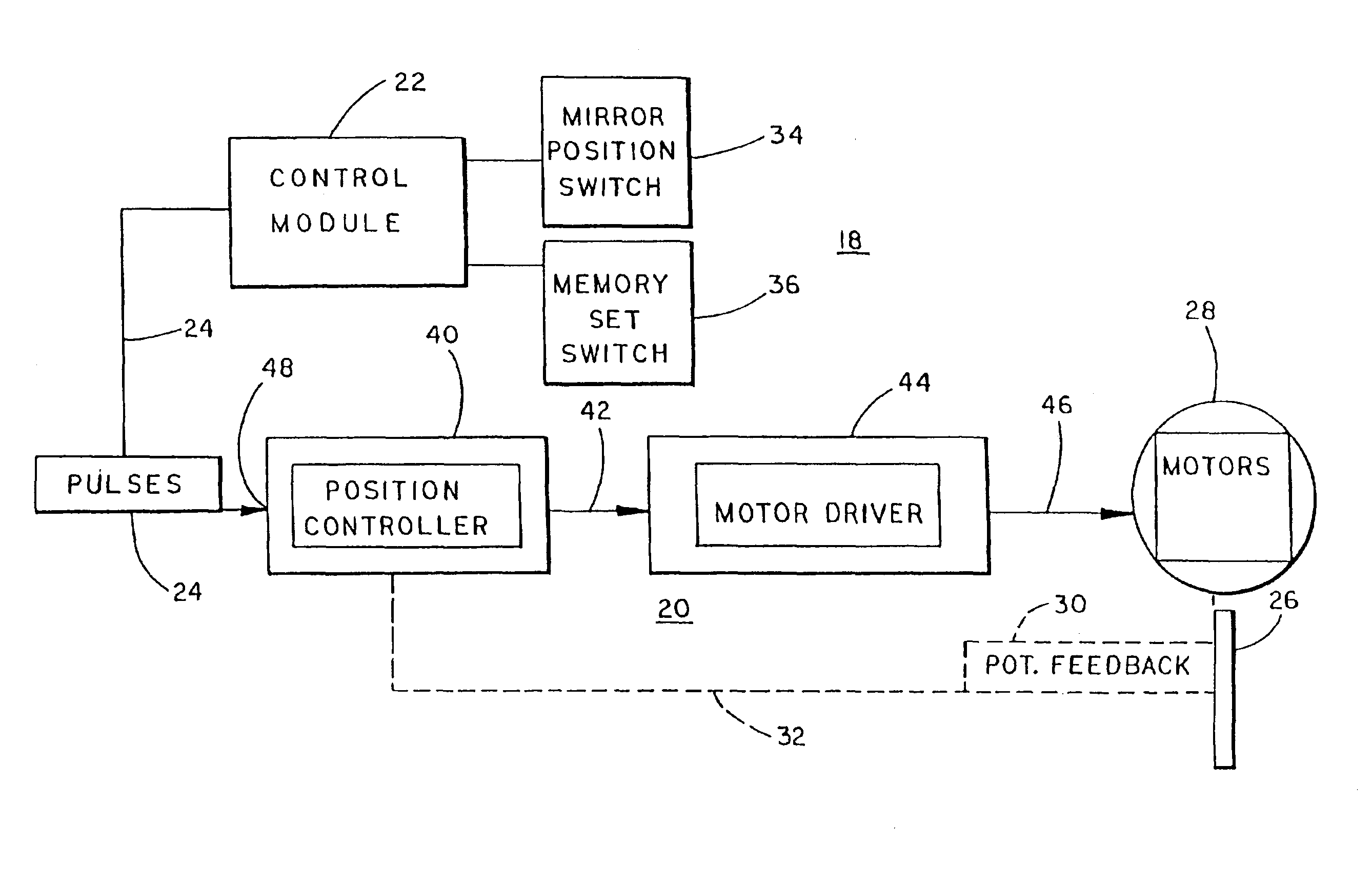
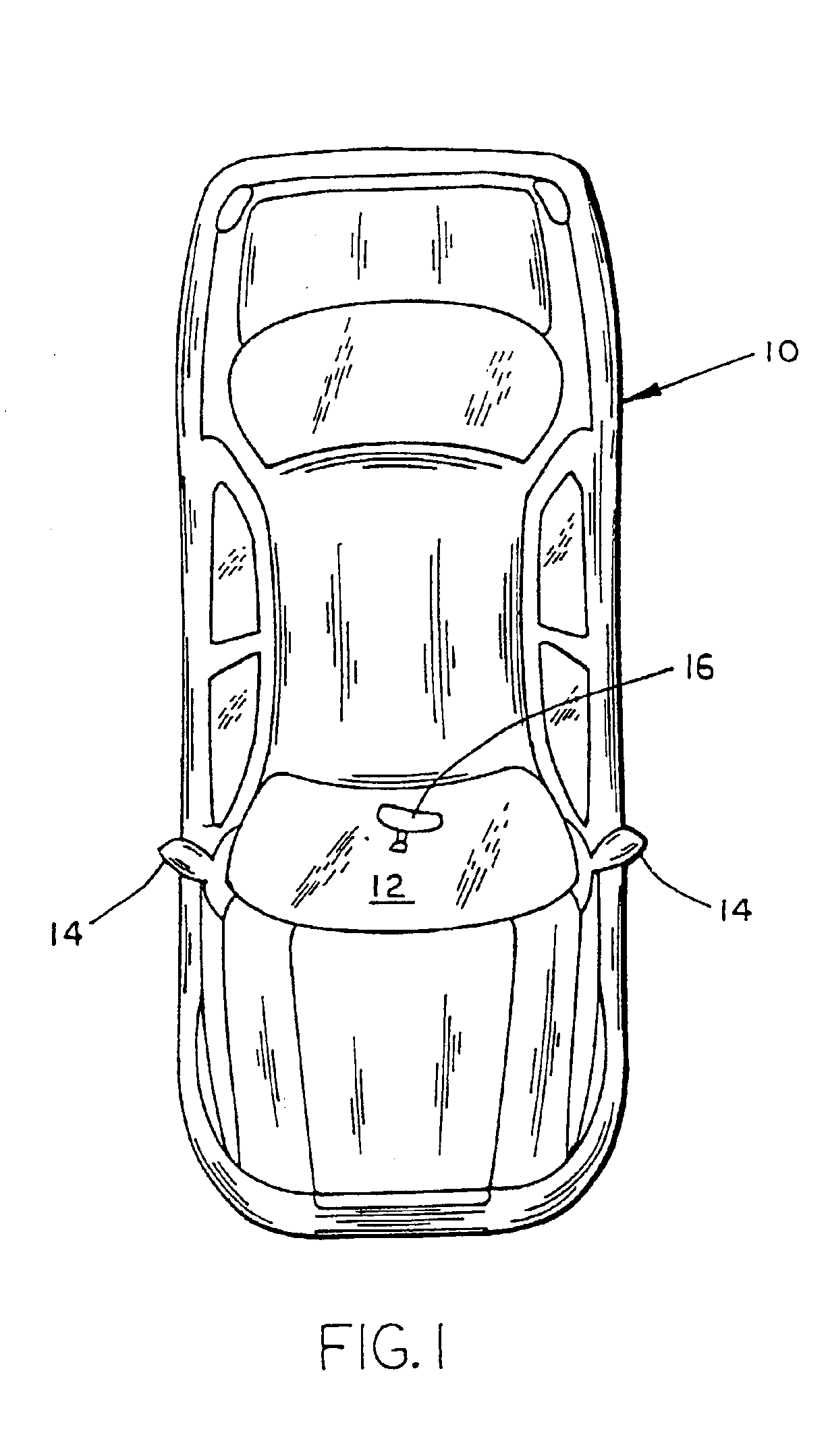
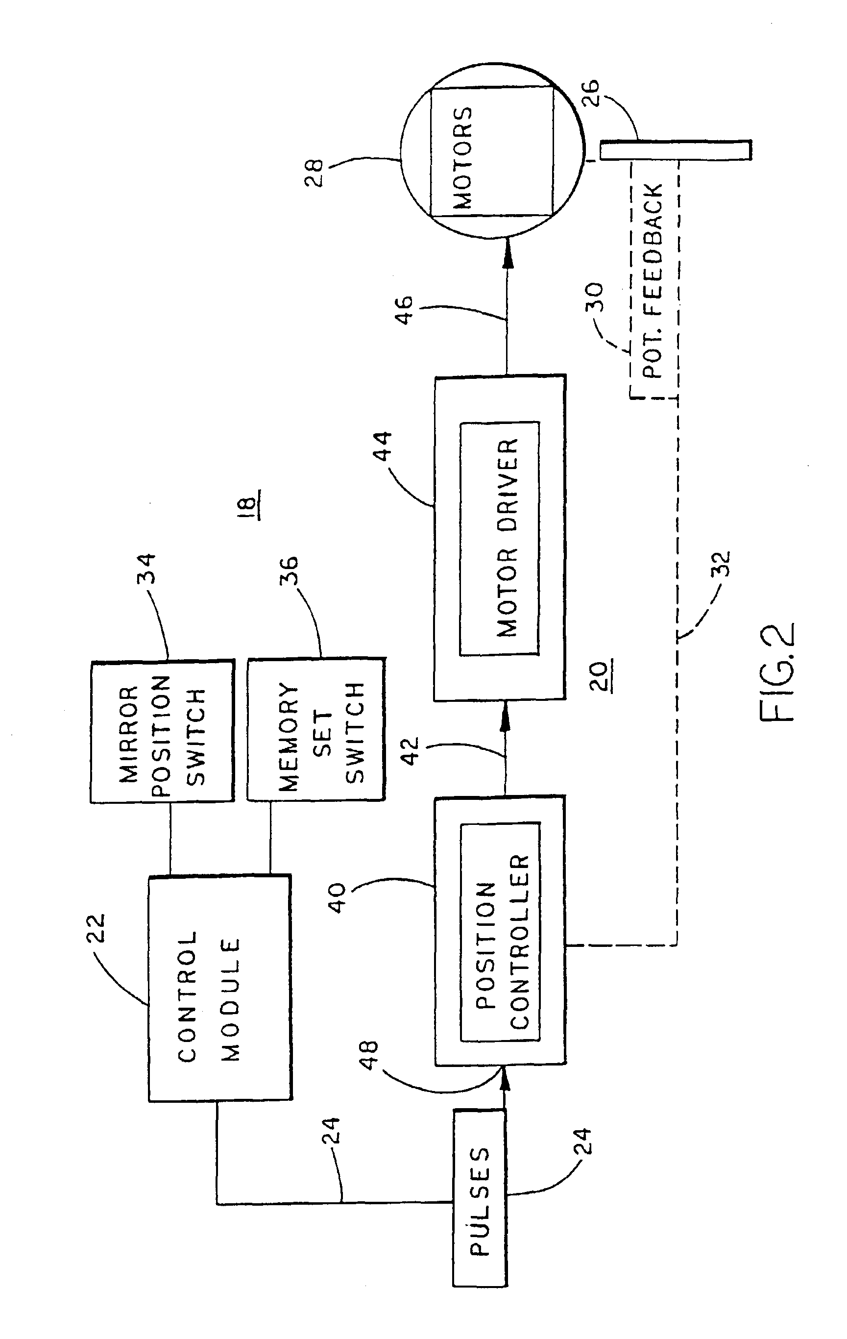
Referring now specifically to the drawings, and the illustrative embodiments depicted therein, a vehicle 10 is illustrated as being equipped with a vehicle memory mirror system 12 including at least one exterior mirror 14 and an interior rearview mirror 16 (FIG. 1). Memory mirror system 12 includes an electronic control system 18 made up of a mirror-based control module 20 in each exterior rearview mirror 14 and a control module 22 which is interconnected with each mirror-based control module 20 by an analog interface 24 (FIGS. 2-6). Mirror-based control module 20 may be positioned within the mirror housing, or head, of the associated mirror, or may be positioned in the mirror support base. Control module 22 may be located in the vehicle door under the dash, or the like. Control module 22 may be associated with other vehicle control functions such as seat position control, or the like.

Control module 22 includes a processor 23 which produces analog signals on each analog interface 24...


PUM


Abstract

A vehicle memory mirror system includes a vehicle mirror assembly and a control module. The vehicle mirror assembly includes a reflective element, a motor for positioning the reflective element about an axis, a monitor for monitoring the position of the reflective element with respect to the axis, and a mirror-based control including a position control which is operatively connected with the motor and the monitor in order to position the reflective element at a particular position. The control module is interconnected with the mirror-based control by an analog interface and includes a processor for providing analog signals on the analog interface indicative of a desired position of the reflective element with respect to the axis. The mirror-based control preferably includes a servo-amplifier circuit. The control module can control the speed of movement by formatting a series of sequential signals on the interface, each representing an incremental movement of the reflective element.

Description

BACKGROUND OF THE INVENTIONThis invention relates generally to vehicle rearview mirror systems and, more particularly, to vehicle memory mirror systems.Vehicle memory mirror systems include at least one, and preferably two, electrically operated motors, each of which positions the reflective element with respect to a given axis. By positioning the reflective element about two generally perpendicular axes, the plane of the mirror can be fully positioned. A user-operable switch, such as a joystick or switch pod, is useful to automatically position the mirrors. In a memory mirror system, a monitor device, such as a potentiometer which is coupled to the reflective element, produces a signal indicative of the position of the reflective element with respect to each axis of movement. The signal produced by the monitor device is used in a closed-loop control to allow a controller to reliably position the mirror to particular positions. In this manner, positions of the mirror for different d...

Claims


Application Information

Patent Timeline
IPC IPC(8): B60R1/02B60R1/00B60R1/12B60R1/062B60R1/07B60R16/02B60R16/037
CPCB60R1/02B60R1/07B60R16/037B60R1/12B60R1/1207
Inventor KRAMER, MARK E.VELDMAN, ROGER L.
Owner DONNELLY CORP
Why Eureka
Try Eureka