
Multiplexer for providing non-equidistant intervals between pump wavelengths in broadband raman amplifiers

a broadband raman amplifier and multi-channel technology, applied in the field of multi-channel amplifiers, can solve the problems of deterioration of optical signal-to-noise ratio osnr, weak signal, and relatively small power which can be injected into the optical waveguide via interference filters

Inactive Publication Date: 2005-03-15
NOKIA SIEMENS NETWORKS GMBH & CO KG
View PDF7 Cites 5 Cited by
  • Summary
  • Abstract
  • Description
  • Claims
  • Application Information

AI Technical Summary

Benefits of technology

This and further aims are achieved by the present invention through a method for producing pump waves for Raman amplification of a signal which is passed via an optical waveguide. The method includes the following steps:provision of a pump wave producing apparatus having at least one pump source which is set up such that it can produce pump waves at a first, a second, a third and a fourth mutually equidistant pump wavelength;driving of the pump wave producing apparatus such that a pump wave is produced in each case at the first, second and fourth pump wavelengths, and in that no pump wave is produced at the third pump wavelength, so that a non-equidistant pump channel pattern is achieved overall.
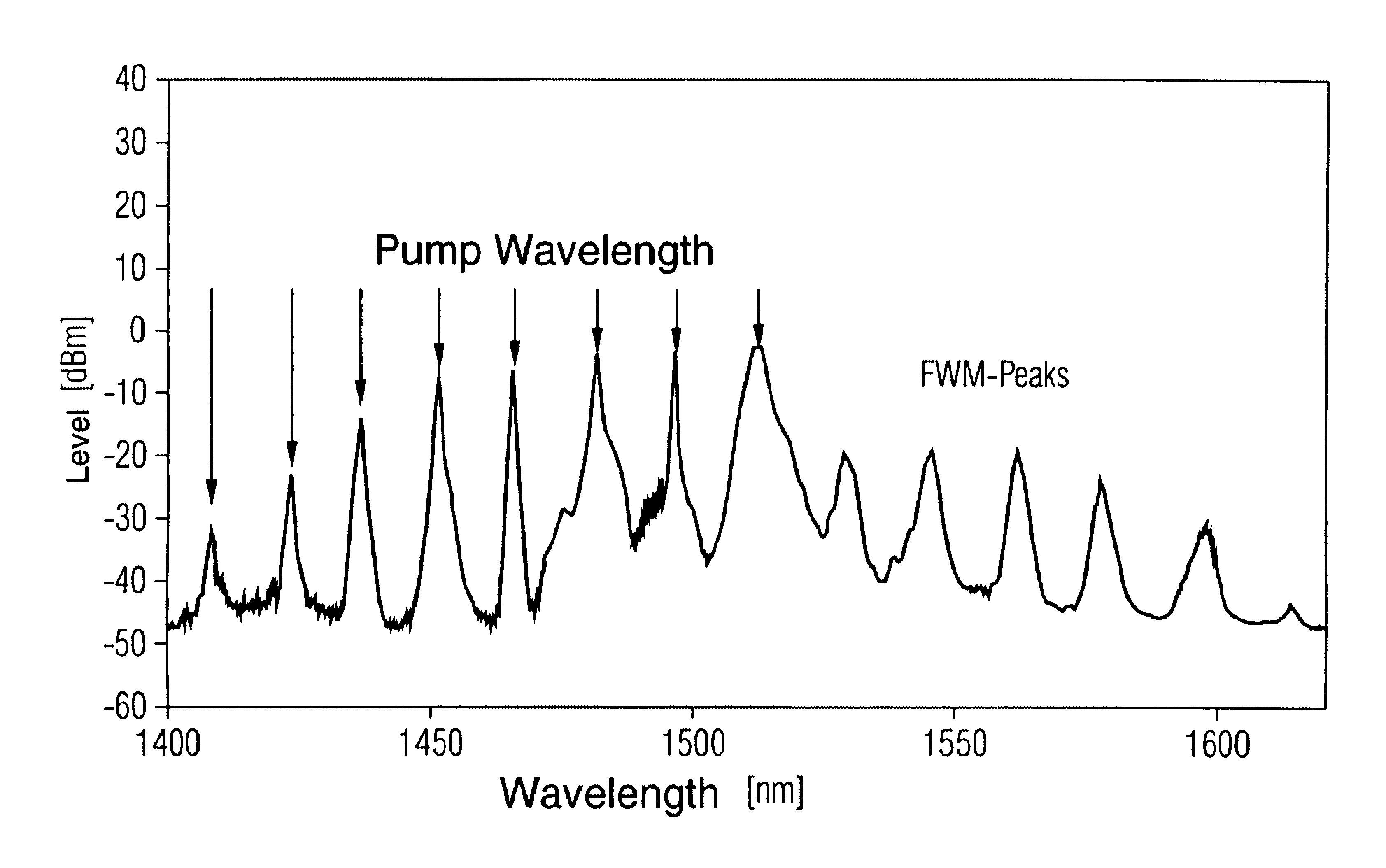
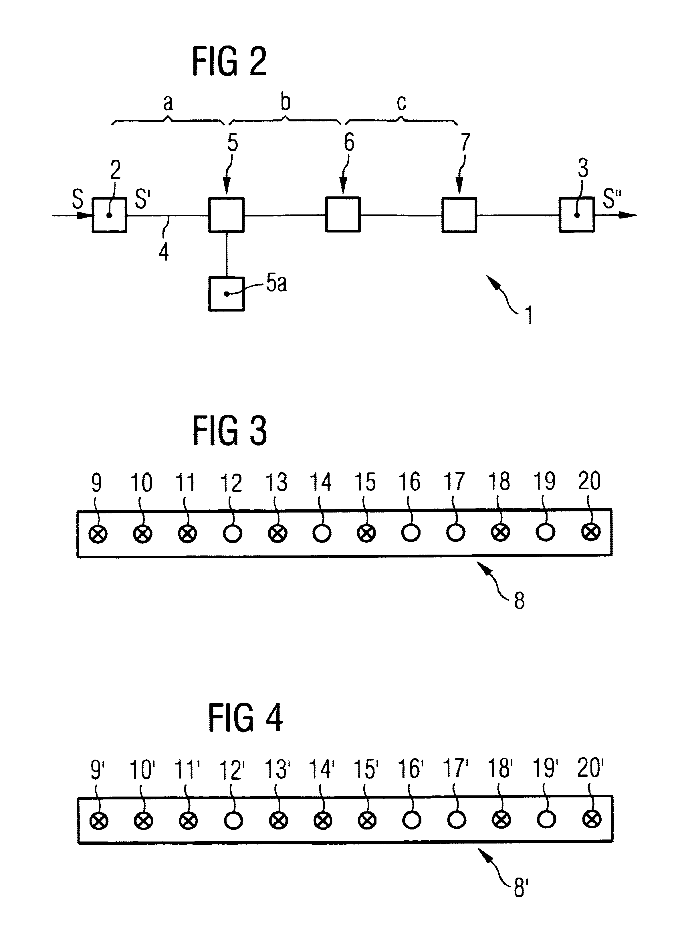
According to an embodiment of the present invention, the pump wave producing apparatus is a Mach-Zehnder interferometer which has more inputs than the number of pump channels to be multiplexed (for example, a Mach-Zehnder interferometer with 12 inputs for 7 or 8 pump wavelengths). A non-equidistant pump channel pattern then can be achieved by choosing the unused inputs such that they are distributed in a correspondingly irregular manner. This reduces the influence of four wave mixing and, hence, increases the optical signal-to-noise ratio OSNR. At the same time, the use of a Mach-Zehnder interferometer makes it possible to inject relatively high pump powers into the optical waveguide.
It is particularly advantageous to use a non-equidistant pump channel pattern for pump waves at relatively long wavelengths, and to use an equidistant pump channel pattern for pump waves at shorter wavelengths. This is because higher local dispersion at relatively short pump wavelengths rapidly leads to divergence of the phase relationships and, hence, to reduced four wave mixing.

Problems solved by technology

When an optical WDM signal (“WDM”=wavelength division multiplex) is transmitted via an optical waveguide, the attenuating characteristics of the optical waveguide lead to the signal becoming weaker.
The four wave mixing that occurs in this case results in a deterioration in the optical signal-to-noise ratio OSNR and, hence, in the signal quality on specific channels in the WDM signal.
However, the power which can be injected into the optical waveguide via interference filters is relatively small.

Method used


Image

  • Multiplexer for providing non-equidistant intervals between pump wavelengths in broadband raman amplifiers
  • Multiplexer for providing non-equidistant intervals between pump wavelengths in broadband raman amplifiers
  • Multiplexer for providing non-equidistant intervals between pump wavelengths in broadband raman amplifiers

Examples


Embodiment Construction

FIG. 2 shows a schematic illustration of an optical message transmission path 1 which has a transmitting device 2, a receiving device 3, an optical waveguide 4, and a number of amplification devices 5, 6, 7.

A received electrical signal S′ is converted to an optical WDM signal S′ in the transmitting device 2 via laser diodes (“WDM”=Wavelength Division Multiplex). The WDM signal S′ is injected into the optical waveguide 4 and is transmitted to the receiving device 3, where it is converted back to an electrical signal S′ via semiconductor diodes.

Owing to the attenuating characteristics of the optical waveguide 4, the WDM signal S′ is weakened in the course of transmission from the transmitting device 2 to the receiving device 3. The WDM signal S′ is therefore amplified, on the basis of stimulated Raman scatter, after a first optical waveguide section a by the amplification device 5, and after further optical waveguide sections b, c by the amplification devices 6, 7.

To this end, each am...


PUM


Abstract

A method for producing non-equidistant pump waves for Raman amplification of a signal which is passed via an optical waveguide, as well as a pump wave producing apparatus for producing pump waves for Raman amplification of a signal which is passed via an optical waveguide, which apparatus has at least one pump source and is set up such that it can produce pump waves at a first, a second, a third and a fourth mutually equidistant pump wavelength, having a control device which is set up such that it causes, in each case, the production of a pump wave u, v, w at the first, second and fourth pump wavelengths, with the control device being set up such that no pump wave is produced at the third pump wavelength, so that a non-equidistant pump channel pattern is achieved overall.

Description

BACKGROUND OF THE INVENTIONThe present invention relates to a method for producing pump waves for Raman amplification of a signal which is passed via an optical waveguide as well as to a pump wave producing apparatus.When an optical WDM signal (“WDM”=wavelength division multiplex) is transmitted via an optical waveguide, the attenuating characteristics of the optical waveguide lead to the signal becoming weaker. The transmitted signal therefore must be amplified after specific optical waveguide sections.One option for signal amplification is based on the use of stimulated Raman scatter. In this case, a pump signal is fed into the optical waveguide. The pump signal is produced via a number of pump sources; for example, a number of laser diodes. In this case, the group of wavelengths from the pump sources is chosen such that, taking account of the Raman gain spectrum, all the channels in the WDM signal are amplified to the same extent (see “Fiber Optic Communication Systems”, G. P Agr...

Claims


Application Information

Patent Timeline
IPC IPC(8): H01S3/30H01S3/094
CPCH01S3/302H01S3/094003H01S3/094096
Inventor EDER, CHRISTIANGENTNER, GUIDONEUHAUSER, RICHARDGAUBATZ, ULRICHKRUMMRICH, PETER
Owner NOKIA SIEMENS NETWORKS GMBH & CO KG
Learn More