Electronic control unit

a control unit and electronic technology, applied in the direction of electrical apparatus construction details, electrical apparatus casings/cabinets/drawers, instruments, etc., can solve the problems of insufficient installation space, small heat transfer amount from heat dissipating devices mounted on circuit boards to the chassis, and inability to achieve sufficient installation space, so as to improve the effect of heat dissipation ability

Inactive Publication Date: 2005-03-15
DENSO CORP
View PDF15 Cites 19 Cited by
  • Summary
  • Abstract
  • Description
  • Claims
  • Application Information

AI Technical Summary

Benefits of technology

It is, therefore, an object of the invention to provide an electronic control unit that can be installed on a high temperature heat source, or in its vicinity, that exhibits an improved heat dissipation ability within its installation environment.
Then the heat transfer by radiation to the chassis from a high temperature heat source such as an internal combustion engine can be lowered, while the heat transfer to the side away from the high temperature source can be augmented. As a result of the decreased heat transfer from an external high temperature source or a high temperature substance and the increased heat transfer to the side away from the high temperature substance, the heat dissipation from the chassis can be accelerated. For example, the electronic devices such as semiconductor switching devices mounted on the circuit board of an electronic control unit can be efficiently cooled.
According to a third aspect of the present invention, one of the surfaces of the chassis is a natural surface of the material forming the chassis and the other surface is subject to a predetermined surface treatment. It then becomes possible to provide an inexpensive chassis that decreases heat transfer from the high temperature substance and increases heat transfer from the chassis to the side opposite to the high temperature substance.
According to a fourth aspect of the present invention, the outer surfaces of the chassis are subject to surface treatments different from each other. Then it becomes possible to increase heat transfer from the chassis to an area outside of the chassis as well as to decrease heat transfer from the high temperature substance and to increase heat transfer to the side opposite to the high temperature substance. For example, the natural metallic surface, which has a low infrared absorption coefficient, of the metal composing the chassis may be treated with a white coating for low infrared absorption and high emissivity. Because heat transfer from the chassis to an area outside of the chassis is enhanced, heat dissipation from the chassis can be further accelerated.
According to a fifth aspect of the present invention, the inner surface of the chassis is subject to a surface treatment for increasing the infrared absorption coefficient. Then the heat transfer to the chassis by radiation from the heat dissipating electronic devices, such as semiconductor switching devices mounted on the circuit board of the electronic control unit, is accelerated. As a result, the device temperature can be lowered.
It then becomes possible to decrease heat transfer from the high temperature heat source to the chassis and at the same time increase heat transfer from the chassis to the side away from the high temperature heat source when heat moves from the high temperature heat source to the chassis. For example, the chassis can be partitioned into a plurality of segments and the segments can be efficiently cooled.

Problems solved by technology

In prior art configurations, because the surface of the metal components forming the chassis is a natural metallic surface, the amount of heat transfer to the chassis from the heat dissipating devices mounted on the circuit board is small.
However, the component structure can become complex and sufficient installation space must be ensured if the heat transfer from heat dissipating devices to the chassis is to be realized by heat conduction via the circuit board, for example.
It then becomes difficult to reduce the size of the electronic control unit.

Method used


Image

  • Electronic control unit
  • Electronic control unit
  • Electronic control unit

Examples


first embodiment

[First Embodiment]

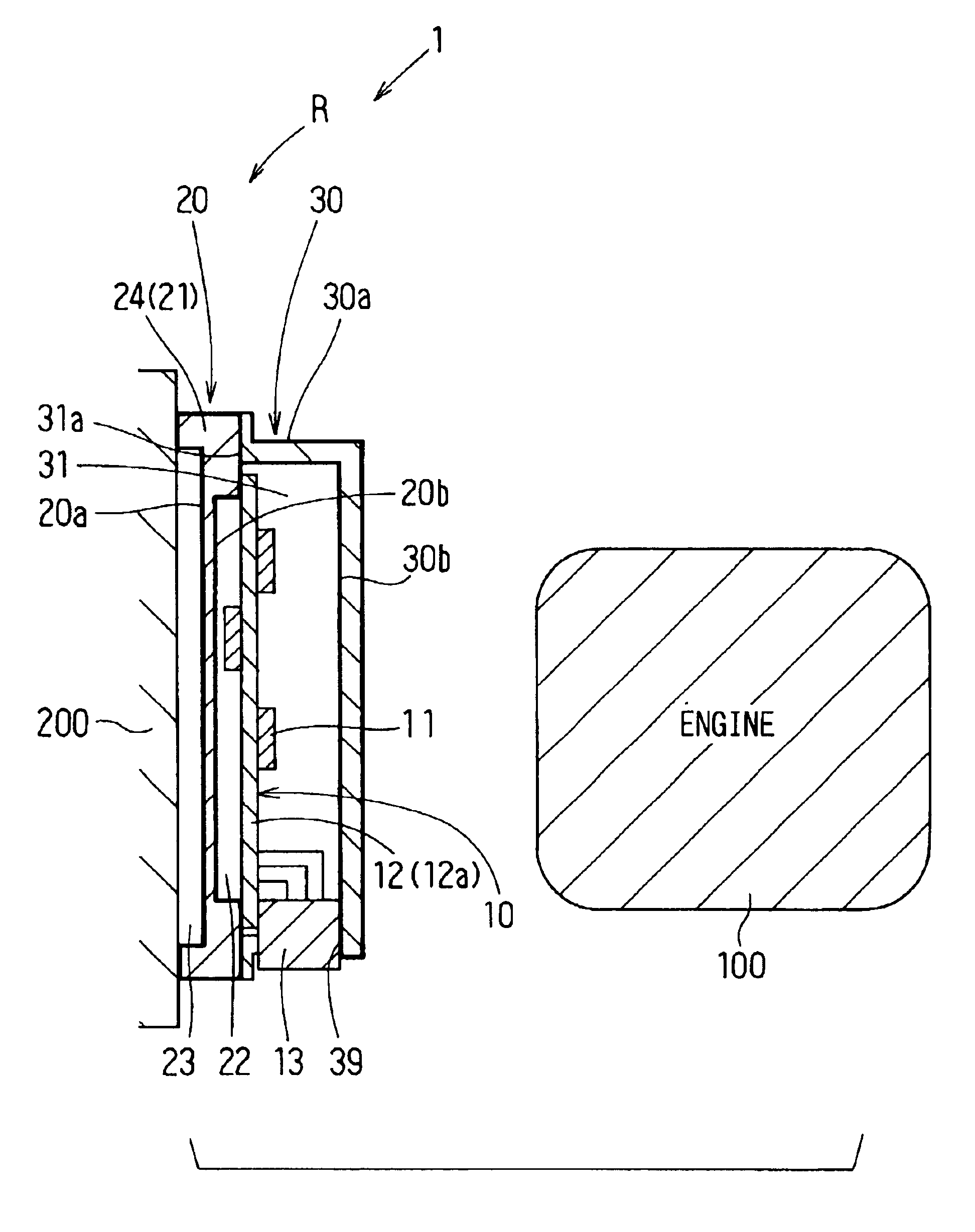
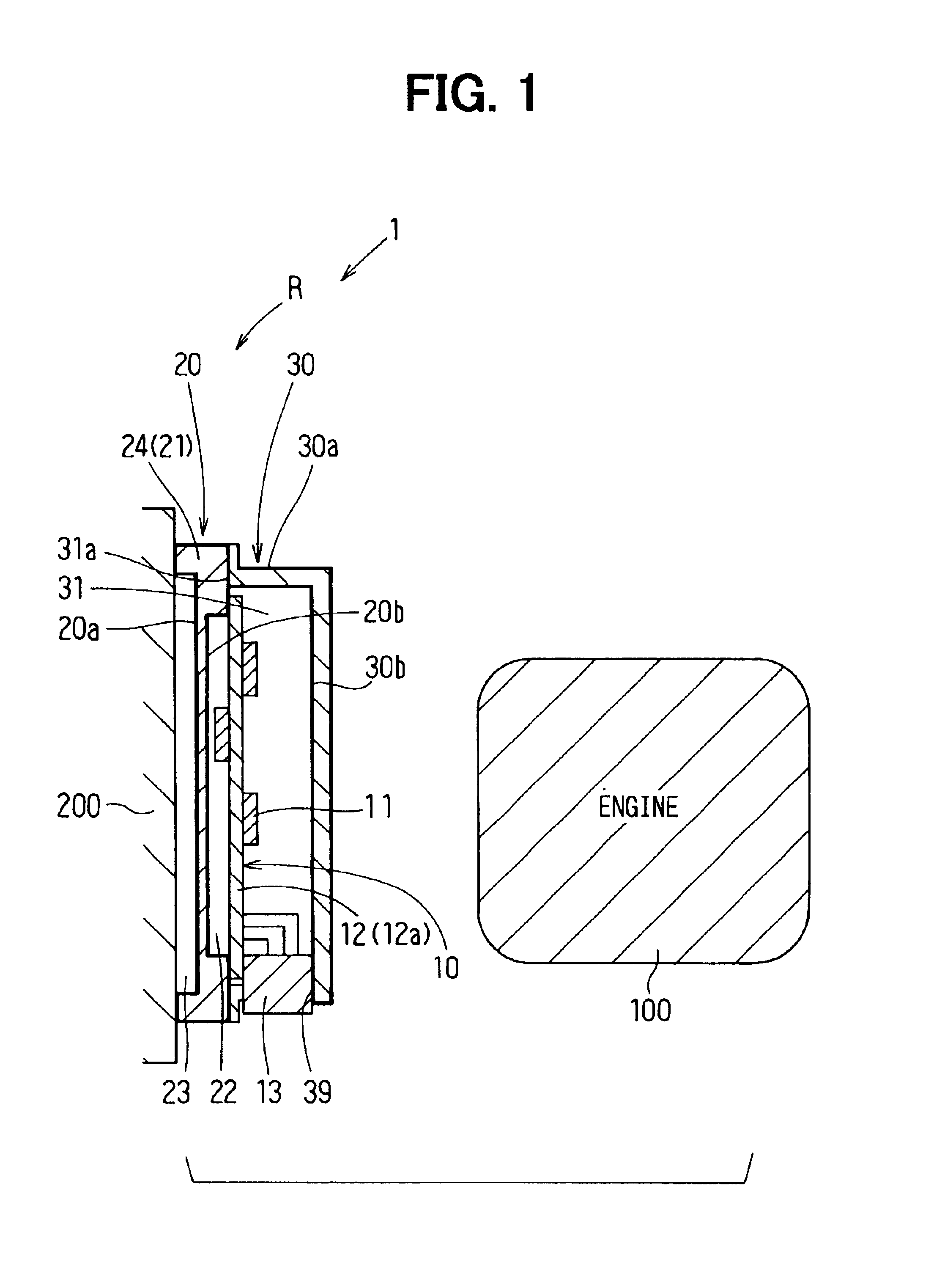
FIG. 1 is a cross-sectional view of an electronic control unit according to a first embodiment of the invention, and FIG. 2 is an exploded perspective view of the electronic control unit of FIG. 1.

As shown in FIG. 1 and FIG. 2, the electronic control unit 1 comprises a circuit board 10 on which are mounted electronic devices 11 such as IC and semiconductor devices, a first housing unit 20 holding the circuit board 10 where these electronic devices 11 are mounted, and a second housing unit 30 incorporating the circuit board 10 in combination with the first housing unit 20. The electronic control unit, which is a control device that controls internal combustion engines and the like, conducts the PWM (pulse width modulation) or PFM (pulse frequency modulation) control on known fuel injection means (not shown) for injecting fuel into the internal combustion engine in response to its rotation speed, load and other factors. The electronic control unit also controls well-...

second embodiment

[Second Embodiment]

FIG. 3 is an exploded perspective view of the electronic control unit in accordance with the second embodiment. In the second embodiment, the outer surface 30a (of the chassis R) on the side of the internal combustion engine 100 (as referred to in the first embodiment) is not a natural metallic face (presenting a metallic color) but a face subject to a surface treatment. The natural metallic surface of the metal forming the chassis R, which has a low infrared absorption ability, now has a white coating, for example, having a low absorption coefficient and a high emissivity. Accordingly, heat transfer from the chassis R to the outside can be accelerated. In addition to the reduction of heat transfer from the high temperature substance (to the chassis R) and the increase of heat transfer from the chassis to the side opposite to the high temperature substance, the function of increasing overall heat transfer from the chassis R to the outside is provided. Consequently...

third embodiment

[Third Embodiment]

FIG. 4 is a cross-sectional view illustrating the structure of the electronic control unit in accordance with the third embodiment. In the third embodiment, the chassis R described in the first embodiment is mounted on the internal combustion engine 100, instead of the vehicle body 200, as is shown in FIG. 4.

With continued reference to FIG. 4, the outer surface 20a on the side facing the internal combustion engine 100, of the outer surfaces of the chassis R (specifically the outer surface 30a of the case 30 and the outer surface 20a of the cover 20), has a white coating, for example, possessing a low absorption coefficient and a high emissivity. On the other hand, the outer surface 30a on the side away from the internal combustion engine 100 has a black coating, for example, with a high emissivity. Then, as is the case with the first embodiment, the resulting chassis R decreases heat transfer to the chassis from the high temperature heat source 100 (high temperatur...


PUM


Abstract

An electronic control unit installed on a high temperature heat source or in its vicinity exhibits an improved heat dissipation ability within its installation environment. The electronic control unit has a chassis incorporating a printed circuit board where electronic devices are mounted. The outer surface of the chassis on the side of the high temperature heat source has a coating for lowering infrared absorption, while the outer surface of the chassis on the side away from the high temperature heat source has a coating for enhancing heat emissivity. Preferably, the inner surfaces of the chassis are subject to a surface treatment for increasing infrared absorption.

Description

CROSS REFERENCE TO RELATED APPLICATIONThis application is based upon, claims the benefit of priority of, and incorporates by reference the contents of prior Japanese Patent Application 2001-394689 filed on Dec. 26, 2001.BACKGROUND OF THE INVENTION1. Field of the InventionThis invention relates to electronic control units, and more specifically, to electronic control units that are located in, or in the vicinity of, a high temperature heat source such as an internal combustion engine.2. Description of the Related ArtGenerally, electronic control units, such as those working as control devices for use with internal combustion engines on vehicles, have circuit boards on which are mounted heat dissipating devices such as semiconductor switching devices. These circuit boards are housed in a chassis made of metallic materials such as aluminum alloys. Such electronic control units maintain the heat dissipating devices at temperatures below a predetermined temperature by conducting heat gen...

Claims


Application Information

Patent Timeline
Patent Type & Authority Patents(United States)
IPC IPC(8): H05K5/00H05K7/20
CPCH05K7/20854
Inventor KATSURO, HAJIMEMIZUTANI, AKIHIRO
Owner DENSO CORP
Why Eureka
Try Eureka