
Magnetic logic elements

a logic element and magnetic field technology, applied in the field of magnetic logic elements, can solve the problems of increasing the difficulty of exponential growth, increasing the difficulty of spontaneous creation, and increasing the difficulty of sustaining exponential growth, so as to achieve maximum gap and mitigate the above problems

Inactive Publication Date: 2005-03-15
HORST SIEDLE GMBH & CO KG
View PDF2 Cites 14 Cited by
  • Summary
  • Abstract
  • Description
  • Claims
  • Application Information

AI Technical Summary

Benefits of technology

"The present invention provides an architecture for a logic device that maximizes the gap between the propagation and nucleation fields to mitigate the problems caused by poor coupling between adjacent solitons. The architecture includes a magnetic conduit that can sustain and propagate a magnetic soliton, with nodes and directional changes incorporated to allow for specific logic functions. The conduit can have a continuous track or a combination of discrete magnetic regions. The invention also provides a method for resetting logic devices using a large field. The technical effects of the invention include improved coupling between adjacent solitons, reduced energy discontinuity, and improved performance of logic devices."

Problems solved by technology

Fundamental physical phenomena associated with small particles make this exponential growth increasingly difficult to sustain.
Such spontaneous creation is undesirable as it leads to an erroneous logic state being generated.
An ideal magnetic logic device would have a propagation field very close to zero (solitons propagate completely freely without any resistance to motion) and a very high nucleation field (errors are very difficult to create).
Whilst the field necessary to propagate solitons in a straight line is relatively small, changes in direction, junctions, and logic gates will result in poorer coupling between adjacent solitons.
The resulting energy discontinuity necessitates higher propagation fields, reducing the gap between the propagation and the nucleation fields, and leading to the problems above described.

Method used


Image

  • Magnetic logic elements
  • Magnetic logic elements
  • Magnetic logic elements

Examples


Embodiment Construction

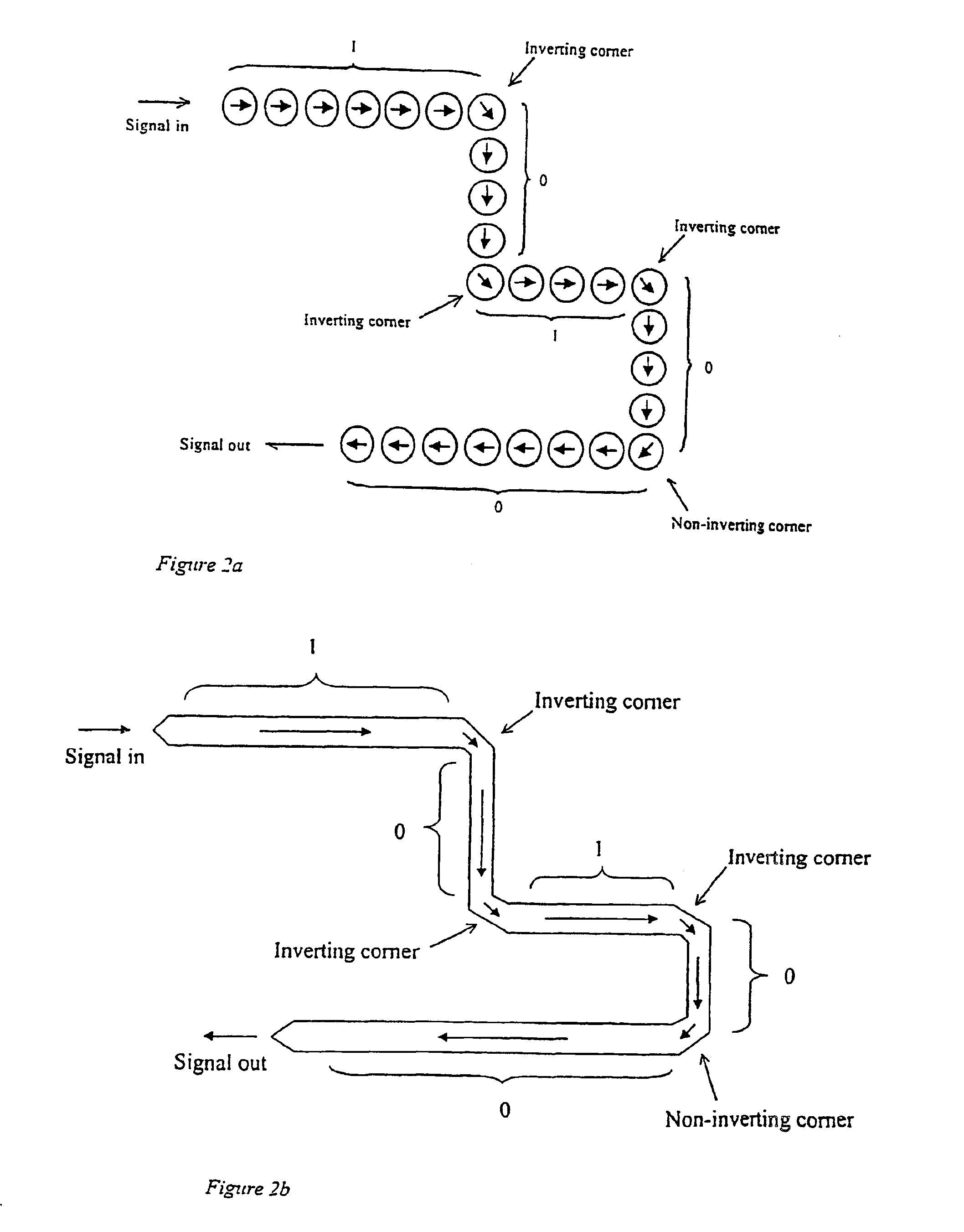
">[0045]FIG. 4 shows a conduit used for carrying solitons in a straight line;

[0046]FIG. 5 shows a unidirectional interconnect (upper and lower) with a schematic graph of the soliton energy as it passes through the interconnect (centre);

[0047]FIG. 6 shows a correctly terminated conduit;

[0048]FIG. 7 shows a symmetric corner;

[0049]FIG. 8 shows an asymmetric corner;

[0050]FIG. 9 shows a two-phase fan-out allowing a signal to split to two signals of opposite phase;

[0051]FIG. 10 shows a one-phase fan-out allowing a signal to split to two signals of same phase;

[0052]FIG. 11 shows a cross-road, allowing two signal lines to cross each other in the same plane;

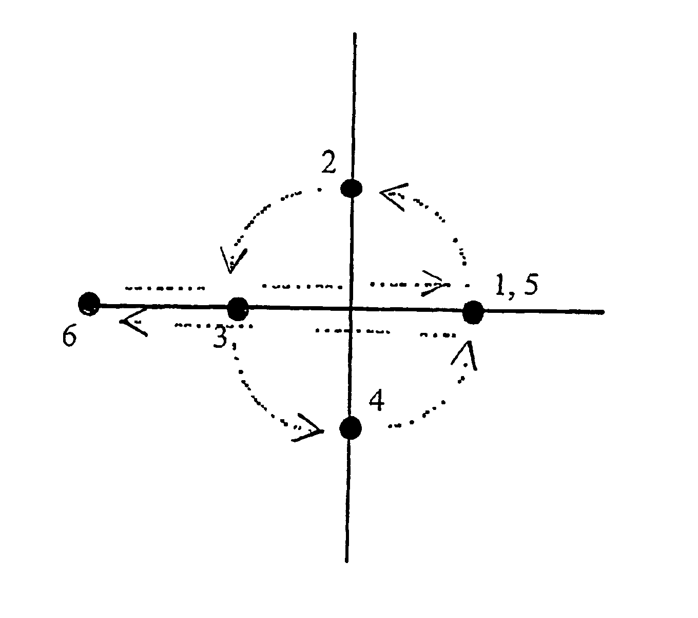
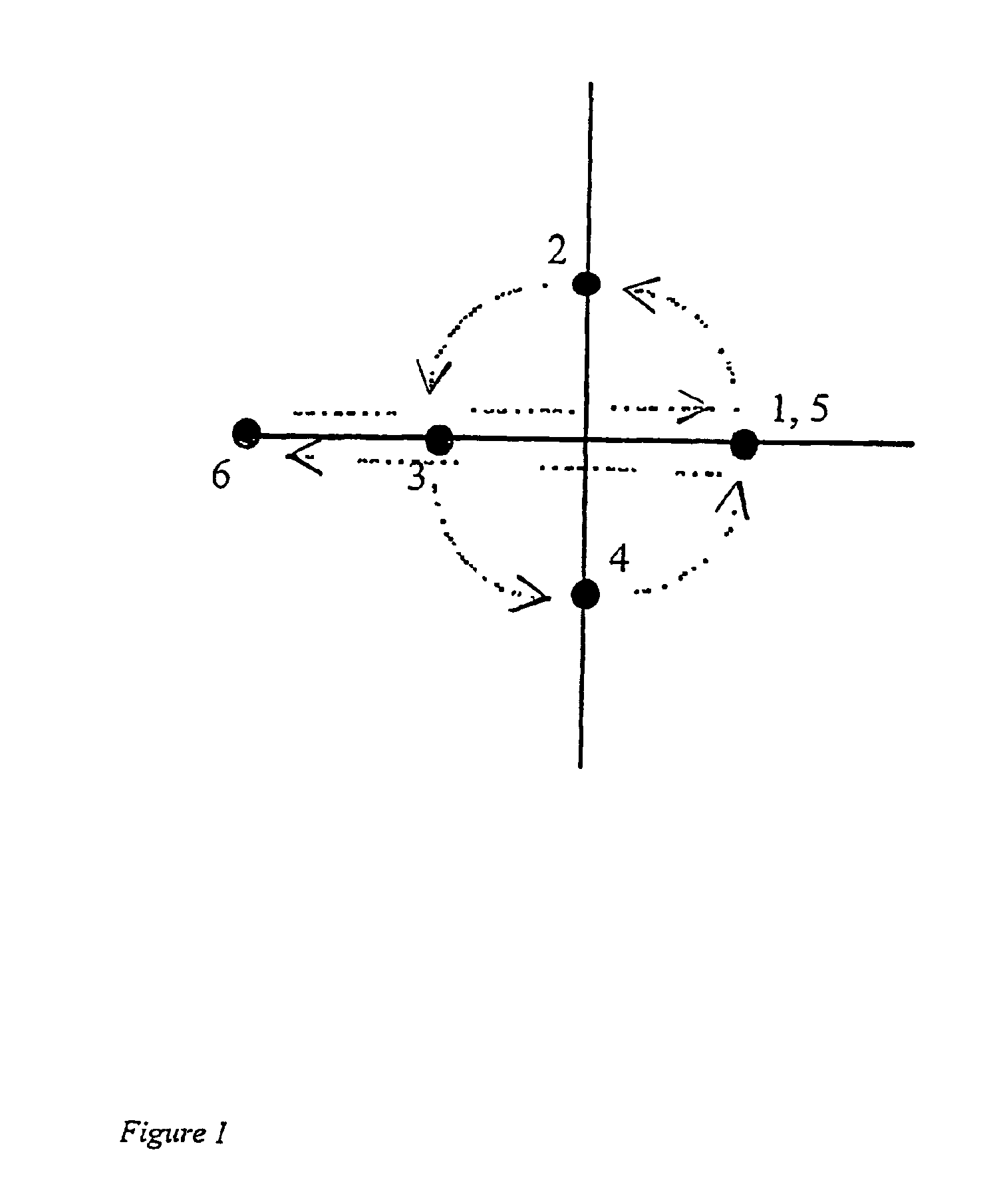
[0053]FIG. 12 shows an AND / OR gate architecture, arranged so that the gate will perform the AND function when the clock field sequence is as shown in FIG. 1;

[0054]FIG. 13 shows the AND / OR gate of FIG. 12 arranged in the reverse direction so that the gate will perform the OR function when the clock field sequence is as shown in FIG. 1;

[005...


PUM


Abstract

A magnetic logic element for a logic device is described formed by at least one conduit capable of sustaining and propagating a magnetic soliton, the conduit being adapted by the provision of nodes and / or directional changes giving rise to discontinuities in soliton propagation energy as a result of which logical functions may be processed. Magnetic logic devices such as interconnects and gates, and magnetic logic circuits incorporating such devices and suitable operational fields, are also described.

Description

RELATED APPLICATIONS[0002]This application is a 35 U.S.C § 371 to PCT / GB01 / 05072, filed Nov. 19, 2001, which claims priority to Great Britain Application No. 0028092.5, filed Nov. 17, 2000.BACKGROUND[0003]1. Field of Invention[0004]The invention relates to the provision of logic elements for logic devices and logic circuitry using the properties of magnetic quantum cellular automata, and in particular to an architecture for the design of such logic elements and devices and for the design and operation of logic circuitry using such elements.[0005]2. Description of Related Art[0006]The number of transistors on a microchip has doubled every 18 months for the past 30 years, a phenomenon known as ‘Moore's Law’. Fundamental physical phenomena associated with small particles make this exponential growth increasingly difficult to sustain. One option already being considered by the semiconductor memory industry is to incorporate nanometre sized magnetic particles (‘nanomagnets’) into microel...

Claims


Application Information

Patent Timeline
Patent Type & Authority Patents(United States)
IPC IPC(8): G06N1/00G11C13/02G11C19/00G11C19/08H03K19/02H03K19/18G06N99/00G11C11/14B82B1/00
CPCB82Y10/00G06N99/002H03K19/18G11C19/0816G11C11/14G11C2213/81G06N10/00G06N99/00
Inventor COWBURN, RUSSELL PAUL
Owner HORST SIEDLE GMBH & CO KG
Learn More