Turbine containing system and an injector therefor

a technology of a containing system and a cylinder head, which is applied in the ignition of the turbine/propulsion engine, engine starters, lighting and heating apparatus, etc., can solve the problems of significant nox formation and ineffective lean premixed combustion, and achieve the effects of reducing cross-sectional area, reducing distance from the coupling, and reducing cross-sectional area

Inactive Publication Date: 2005-03-22
GENERAL ELECTRIC CO
View PDF43 Cites 238 Cited by
  • Summary
  • Abstract
  • Description
  • Claims
  • Application Information

AI Technical Summary

Benefits of technology

In a preferred embodiment, the injector includes a fuel recirculation zone prevention means. Such a means is any structure that prevents flow separation that leads to recirculation at any location within the injector to thereby prevent the occurrence of an auto-ignition event in the injector before the fuel passing through the exits of the injector. A structure that accomplishes the function is flaring member between the coupling and the start of the exits in the injector.

Problems solved by technology

Even with this technology, for the most advanced high efficiency heavy duty industrial gas turbines, the required temperature of the products of combustion at the combustor exit / first stage turbine inlet at maximum load is so high that the combustor must be operated with peak gas temperature in the reaction zone which exceeds the thermal NOx formation threshold temperature resulting in significant NOx formation even though the fuel and air are premixed lean.
The problem to be solved is to obtain combustor exit temperatures high enough to operate the most advanced, high efficiency heavy duty industrial gas turbines at maximum load without forming a significant amount of thermal NOx.
Lean direct injection (LDI) of hydrocarbon fuel and air has also been shown to be an effective method for reducing NOx emission levels for gas turbine combustion systems although not as effective as lean premixed combustion.

Method used


Image

  • Turbine containing system and an injector therefor
  • Turbine containing system and an injector therefor
  • Turbine containing system and an injector therefor

Examples


Embodiment Construction

In the following description, like reference characters designate like or corresponding parts throughout the several views. Also in the following description, it is to be understood that such terms as “forward,”“rearward,”“left,”“right,”“upwardly,”“downwardly,” and the like are words of convenience and are not to be construed as limiting terms.

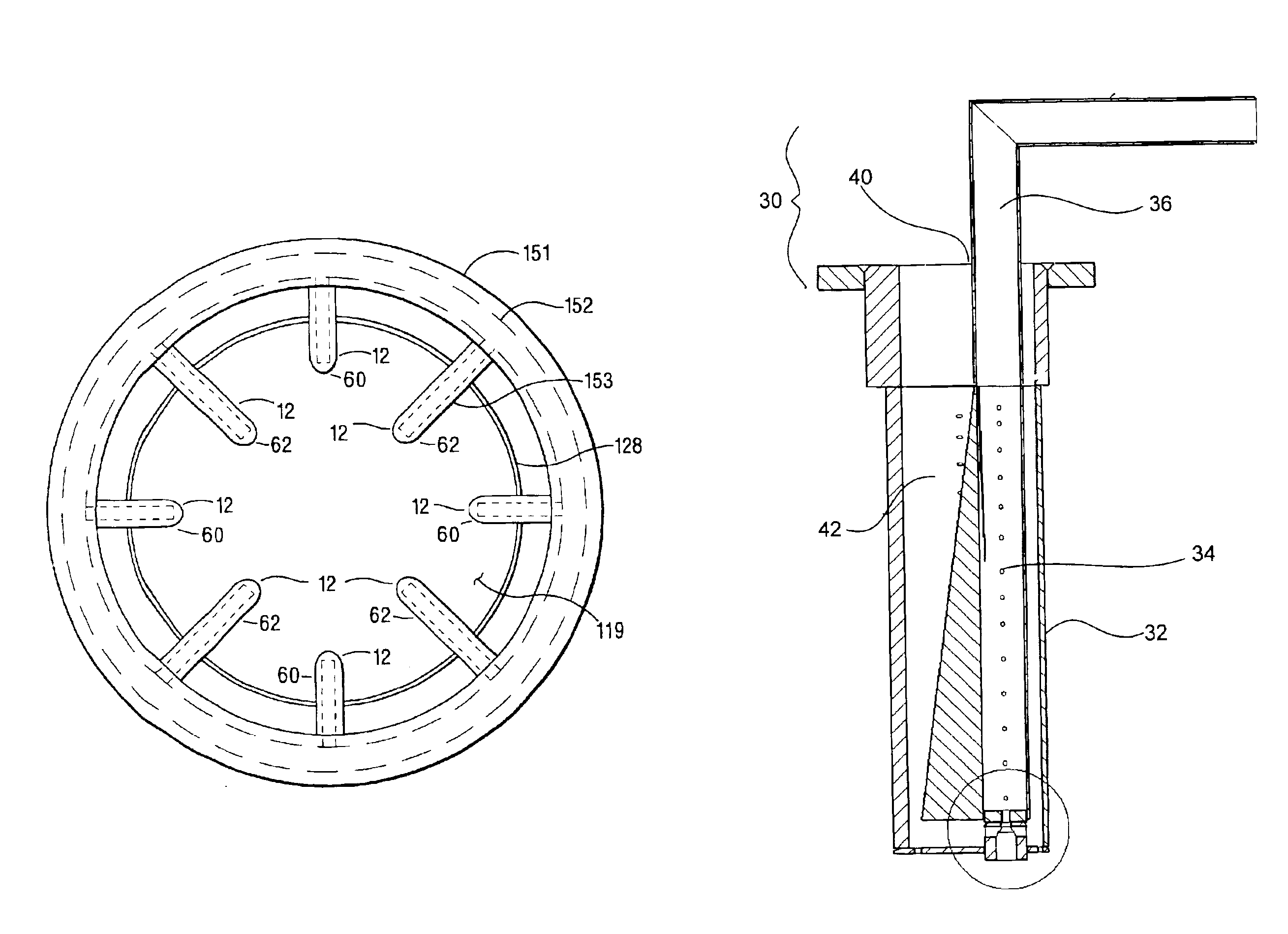
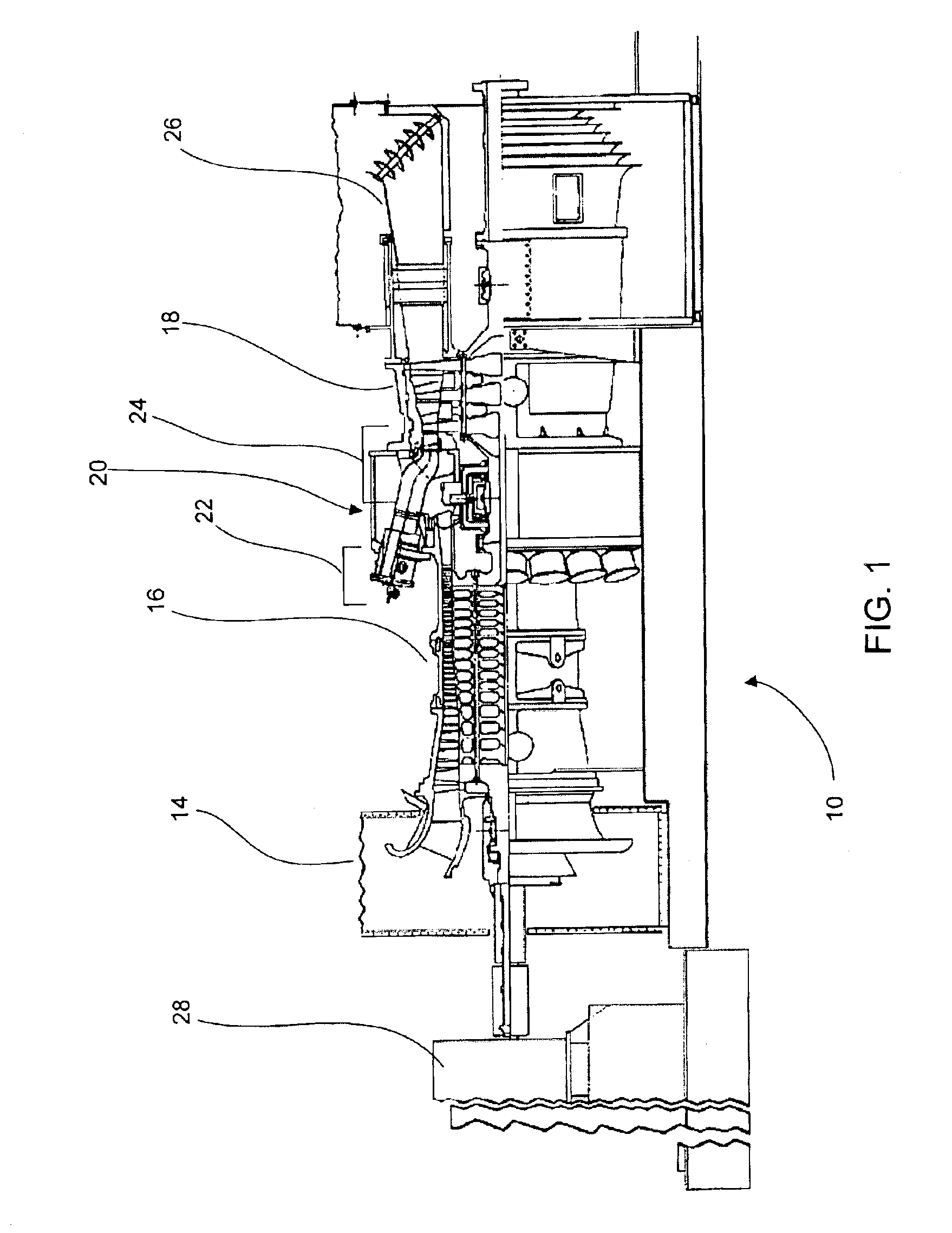
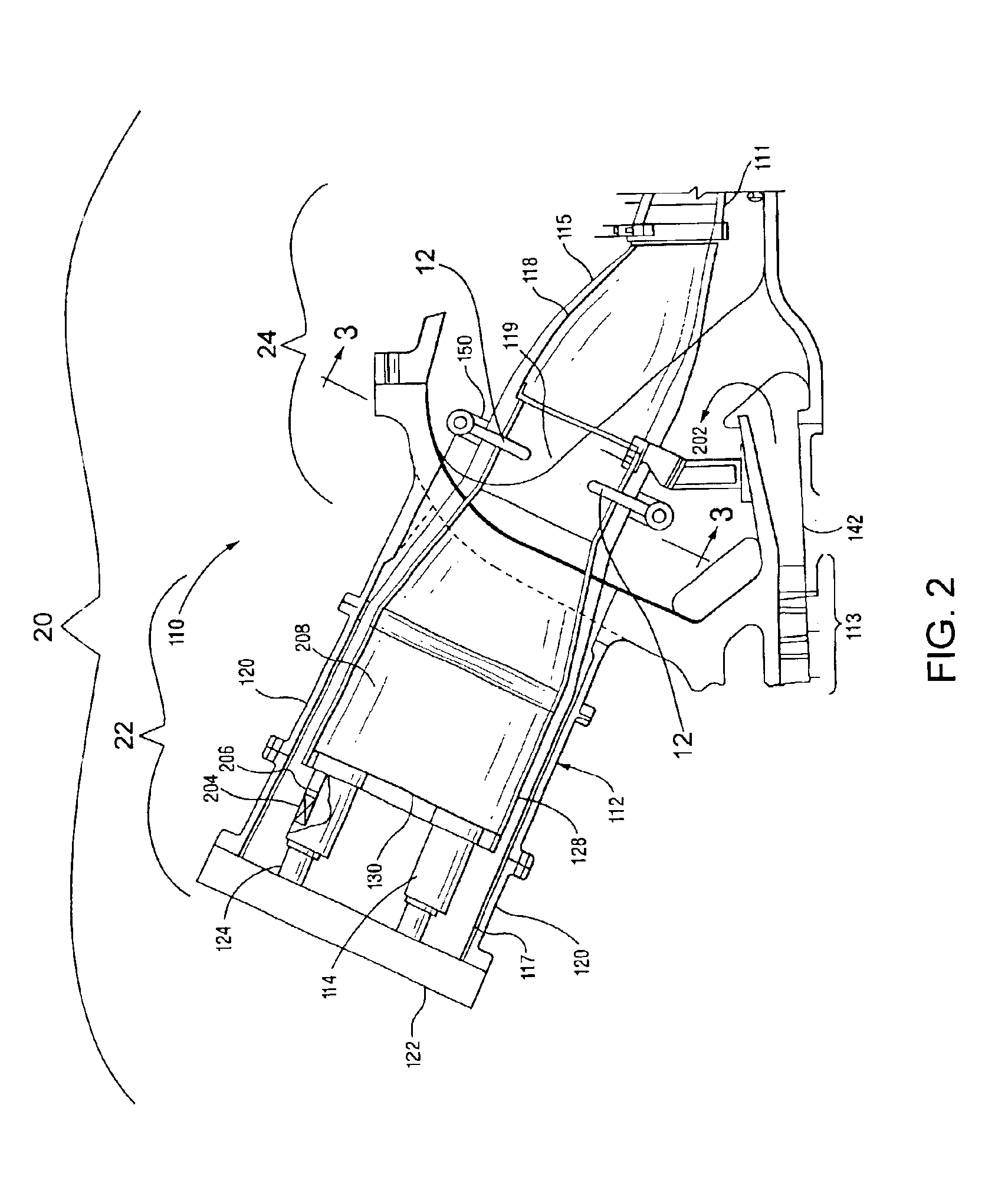
Referring now to drawings in general and FIG. 1 in particular, it will be understood that the illustrations are for the purpose of describing a preferred embodiment of the invention and are not intended to limit the invention thereto. As best seen in FIG. 1, a turbine containing system, indicated generally by the numeral 10, is shown constructed according to the present invention. The turbine containing system, which, in addition to a primary combustion system, includes a secondary combustion system 24 including an injector 12 (not shown) for transversely injecting a secondary fuel mixture into a stream of combustion products of the primary co...


PUM


Abstract

A turbine containing system is disclosed. The system includes an intake section, a compressor section downstream from the intake section, a combustor section having a primary combustion system downstream from the intake section, a secondary combustion system downstream from the primary combustion system, a turbine section, an exhaust section and a load. The secondary combustion system includes an injector for transversely injecting a secondary fuel into a stream of combustion products of the primary combustion system. The injector including a coupling, a wall defining an airfoil shape circumscribing a fuel mixture passage, and at least one exit for communication between said fuel mixture passage and said stream of primary combustion products.

Description

BACKGROUND OF INVENTIONThis invention relates to a turbine containing system and, more specifically, to a turbine containing system that, in addition to a primary combustion system, includes a secondary combustion system including an injector for transversely injecting a secondary fuel mixture into a stream of combustion products of the primary combustion system.There is a drive within the industry to produce new turbines that will operate at high efficiency without producing undesirable air polluting emissions. The primary air polluting emissions usually produced by turbines burning conventional hydrocarbon fuels are oxides of nitrogen, carbon monoxide and unburned hydrocarbons. It is well known in the art that oxidation of molecular nitrogen in air breathing engines is highly dependent upon the maximum temperature in the combustion system reaction zone and the residence time for the reactants at the maximum temperatures reached within the combustor. The level of thermal NOx format...

Claims


Application Information

Patent Timeline
Patent Type & Authority Patents(United States)
IPC IPC(8): F02C3/00F02C3/14F23R3/02F23R3/20F23R3/34F01D15/08F02C3/16F23R3/28
CPCF02C3/14F23R3/34F23R3/20F23D2900/14004
Inventor HAYNES, JOEL MEIER
Owner GENERAL ELECTRIC CO
Why Eureka
Try Eureka