Refrigeration cycle apparatus

a technology of refrigeration cycle and linear compressor, which is applied in the direction of lighting and heating apparatus, positive displacement liquid engine, heat pump, etc., can solve the problem that the amount of refrigerant circulating in the refrigeration cycle cannot be calculated from the stroke of the piston, and the refrigeration cycle apparatus using the linear compressor cannot perform highly efficient refrigeration cycle control. achieve the effect of high efficiency

Inactive Publication Date: 2005-03-22
PANASONIC CORP
View PDF26 Cites 55 Cited by
  • Summary
  • Abstract
  • Description
  • Claims
  • Application Information

AI Technical Summary

Benefits of technology

The present invention is made to solve the above-described problems and has for its object to provide a refrigeration cycle apparatus using a linear compressor which can control the refrigerating capacity with high efficiency on the basis of a temperature difference between an actual temperature of a room or the like to be cooled or heated and a target temperature thereof.

Problems solved by technology

Therefore, while highly efficient refrigeration cycle control can be carried out in a refrigeration cycle apparatus in which the amount of refrigerant circulating in the refrigeration cycle is set to a constant value according to the rpm of the compressor, it is difficult to carry out highly efficient refrigeration cycle control in a refrigeration cycle apparatus in which the refrigerant circulation amount is not determined by only the rpm of the compressor 56.
Further, since the amount of refrigerant that remains in the compression chamber at the completion of the compressing operation is not constant, the amount of refrigerant circulating in the refrigeration cycle cannot be calculated from the stroke of the piston.
As a result, the refrigeration cycle apparatus using the linear compressor cannot perform highly efficient refrigeration cycle control on the basis of the rpm of the compressor, i.e., the number of reciprocating motions of the piston per unit time.

Method used


Image

  • Refrigeration cycle apparatus
  • Refrigeration cycle apparatus
  • Refrigeration cycle apparatus

Examples


embodiment 1

[Embodiment 1]

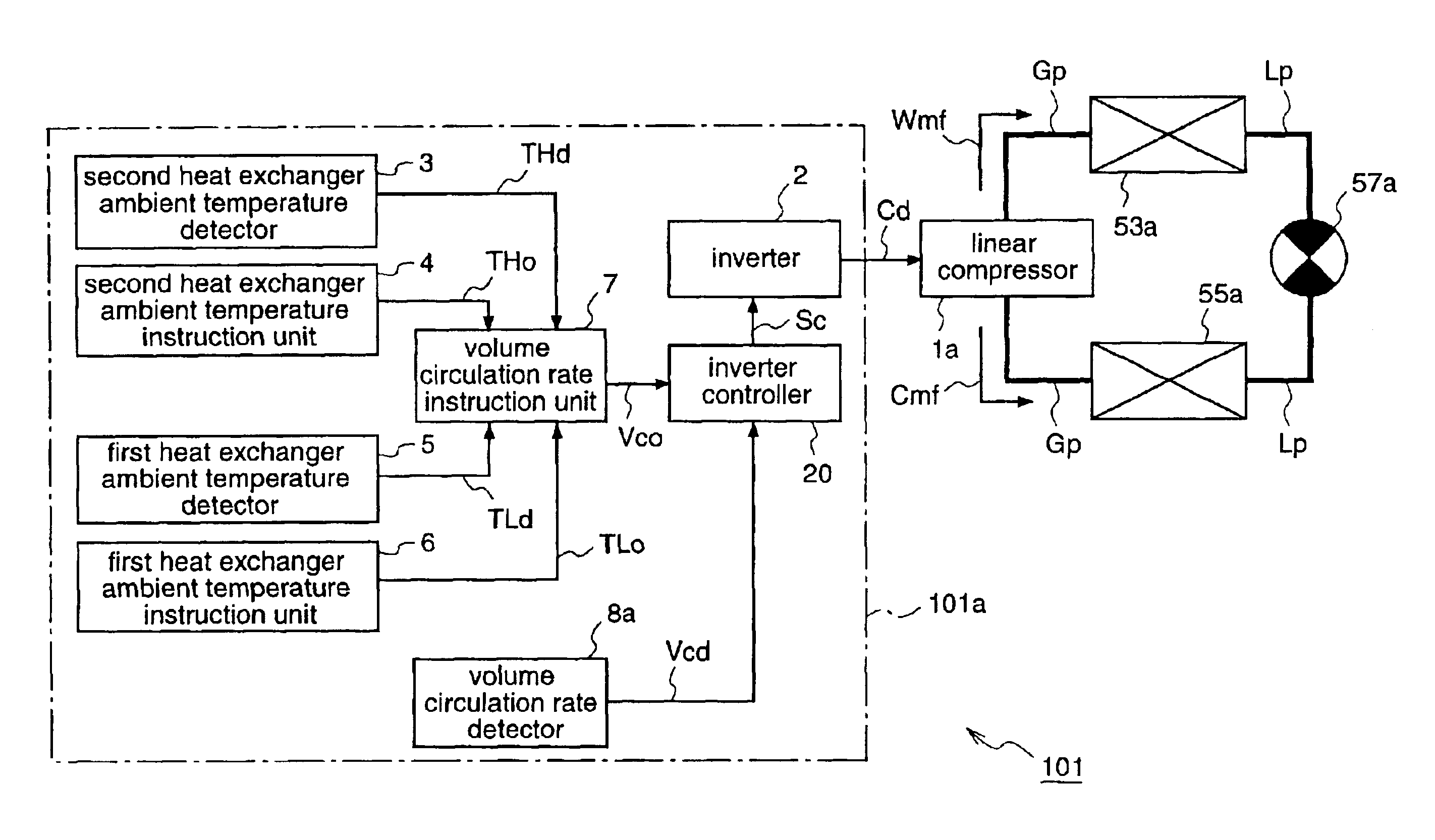
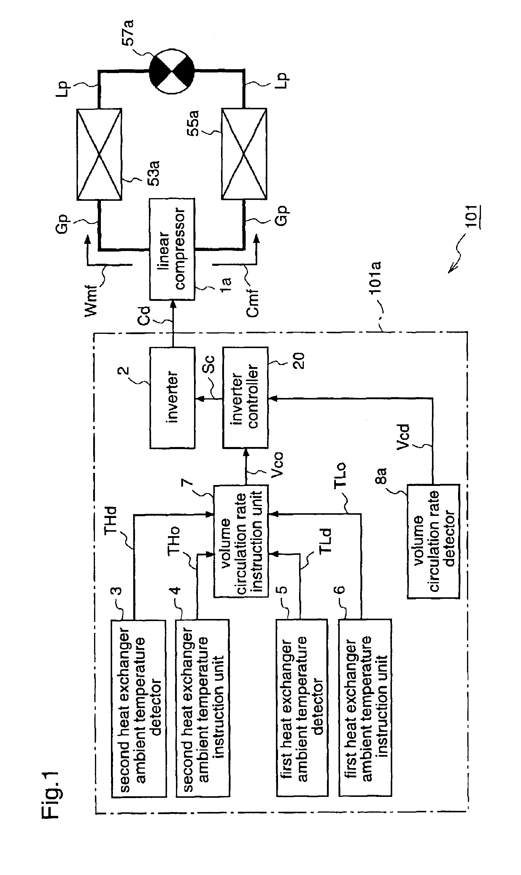
FIG. 1 is a diagram for explaining a refrigeration cycle apparatus according to a first embodiment of the present invention.

A refrigeration cycle apparatus 101 according to the first embodiment of the invention is an air conditioner for cooling a room, and it is provided with, like the conventional air conditioner 50 shown in FIG. 8, a first heat exchanger (evaporator) 53a and a second heat exchanger (condenser) 55a which form a refrigerant circulation path (refrigeration cycle). A linear compressor 1a is placed in a gas flow path Gp connecting both heat exchangers; and a restrictor 57a is placed in a liquid f low pa th Lp connecting both heat exchangers.

The linear compressor 1a is identical to the linear compressor 1 shown in FIG. 11. That is, the linear compressor 1a has a cylinder section 71a including a piston 72, and a motor section 71b including a linear motor 82 for making the piston 72 reciprocate. The linear compressor has a compression chamber 76 formed, in p...

embodiment 2

[Embodiment 2]

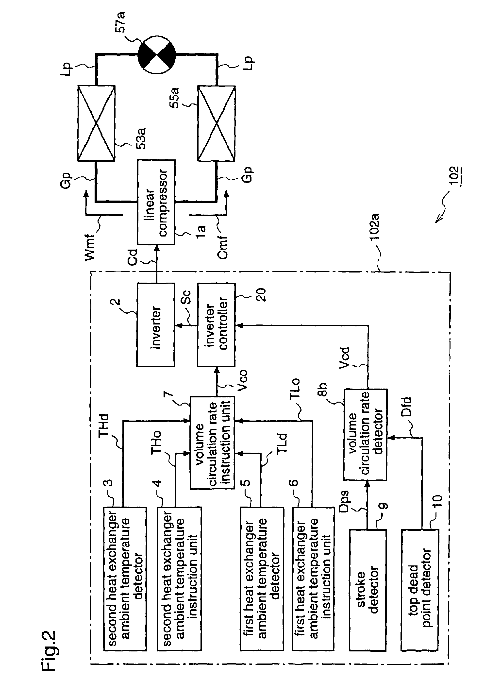
FIG. 2 is a block diagram for explaining a refrigeration cycle apparatus according to a second embodiment of the present invention.

A refrigeration cycle apparatus 102 according to the second embodiment is provided with, instead of the compressor driving unit 101a of the first embodiment, a compressor driving unit 102a which detects the actual volume circulation rate in a manner different from that of the compressor driving unit 101a. The other constituents of the apparatus 102 are identical to those of the first embodiment.

To be specific, the compressor driving unit 102a includes a second heat exchanger ambient temperature detector 3, a first heat exchanger ambient temperature detector 5, a second heat exchanger ambient temperature instruction unit 4, a first heat exchanger ambient temperature instruction unit 6, a volume circulation rate instruction unit 7, an inverter 2, and an inverter controller 20, like the compressor driving unit 101a of the first embodiment.

The ...

embodiment 3

[Embodiment 3]

FIG. 4 is a block diagram for explaining a refrigeration cycle apparatus according to a third embodiment of the present invention, illustrating a linear compressor driving unit as a component of the refrigeration cycle apparatus.

A refrigeration cycle apparatus 103 according to the third embodiment is provided with a linear compressor driving unit 103a for drive-controlling the linear compressor 1a on the basis of the weight circulation rate of the refrigerant per unit time (hereinafter also referred to simply as weight circulation rate), instead of the linear compressor driving unit 101a of the first embodiment for drive-controlling the linear compressor 1a on the basis of the volume circulation rate of the refrigerant per unit time (hereinafter also referred to simply as volume circulation rate). The other components are identical to those of the refrigeration cycle apparatus 101 of the first embodiment.

To be specific, the refrigeration cycle apparatus 103 is an air c...


PUM


Abstract

A refrigeration cycle apparatus having a linear compressor is provided with a volume circulation rate instruction unit for obtaining a volume circulation rate Vco of a refrigerant in accordance with refrigerating capacity required of the refrigeration cycle apparatus, on the basis of an ambient temperature of an indoor heat exchanger (evaporator), a target temperature set on the evaporator by the user, and an ambient temperature of an outdoor heat exchanger (condenser). A volume circulation rate detector is provided for detecting a volume circulation rate Vcd of the refrigerant that actually circulates in a refrigerant circulation path of the refrigeration cycle apparatus; and an inverter is provided for generating an AC current for driving the linear compressor. The inverter is controlled so as to decrease a difference between the volume circulation rate Vco and the volume circulation rate Vcd.

Description

FIELD OF THE INVENTIONThe present invention relates to a refrigeration cycle apparatus and, more particularly, a refrigeration cycle apparatus using a linear compressor which makes a piston in a cylinder reciprocate by a linear motor to generate a compressed gas of a refrigerant.BACKGROUND OF THE INVENTIONConventionally, a refrigeration cycle apparatus employing a linear compressor which utilizes a mechanical elastic member or elasticity of a compressed gas as equipment for generating a compressed gas of a refrigerant, has been known. Concrete applications for such refrigeration cycle apparatus include an air conditioner for cooling or heating a room to keep a comfortable room temperature, a refrigerator for keeping its interior at an appropriate low temperature, and the like.FIG. 11 is a diagram for explaining a linear compressor using a spring as an elastic member, which is used in the conventional refrigeration cycle apparatus.A linear compressor 1 includes a cylinder section 71a...

Claims


Application Information

Patent Timeline
Patent Type & Authority Patents(United States)
IPC IPC(8): F25B1/02F25B49/02F25B30/02F25B30/00F25B13/00
CPCF25B1/02F25B30/02F25B49/022F25B13/00F25B2313/0314Y02B30/741F25B2400/073F25B2600/021F25B2700/2104F25B2700/2106F25B2700/21172F25B2313/0315Y02B30/70F04B17/04
Inventor UEDA, MITSUOYOSHIDA, MAKOTOYAKUMARU, YUUICHI
Owner PANASONIC CORP
Why Eureka
Try Eureka