Coolant motor fan drive

a technology of cooling motors and motor drives, which is applied in the direction of machines/engines, mechanical equipment, transportation and packaging, etc., can solve the problems of system cost and inefficiency, many engine-cooling applications do not allow for conventional mounting of engines, and poor cooling system performan

Active Publication Date: 2005-03-22
BORGWARNER INC
View PDF9 Cites 20 Cited by
  • Summary
  • Abstract
  • Description
  • Claims
  • Application Information

AI Technical Summary

Benefits of technology

In alternative preferred embodiments, because of the huge rpm range of some motors, a dual stage pump is used as either the water pump, water motor, or both the water pump and water motor. The dual stage pump allows for a more varying response between engine speed and pump / fan output.

Problems solved by technology

However, many engine-cooling applications do not allow for conventional mounting of an engine-cooling fan on a water pump.
These systems are costly and inefficient.
Another potential issue related to cooling system performance is electrical power usage.
Further, customer demands for increased horsepower and towing capacity create additional demands on electrical systems.
These extra demands place increased burdens on cooling systems to cool the engine compartment without significantly increasing electrical demand.

Method used


Image

  • Coolant motor fan drive
  • Coolant motor fan drive
  • Coolant motor fan drive

Examples


Embodiment Construction

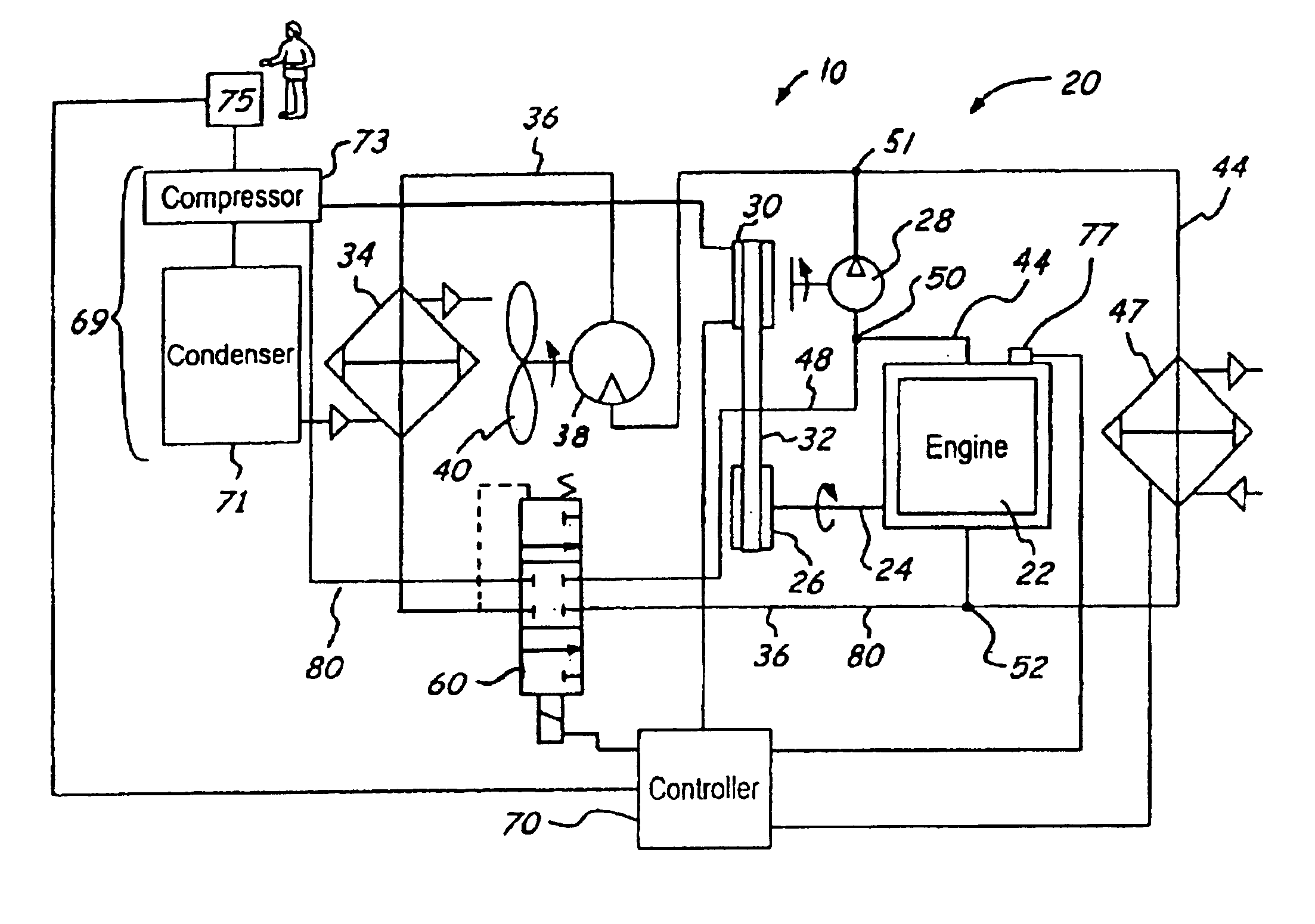
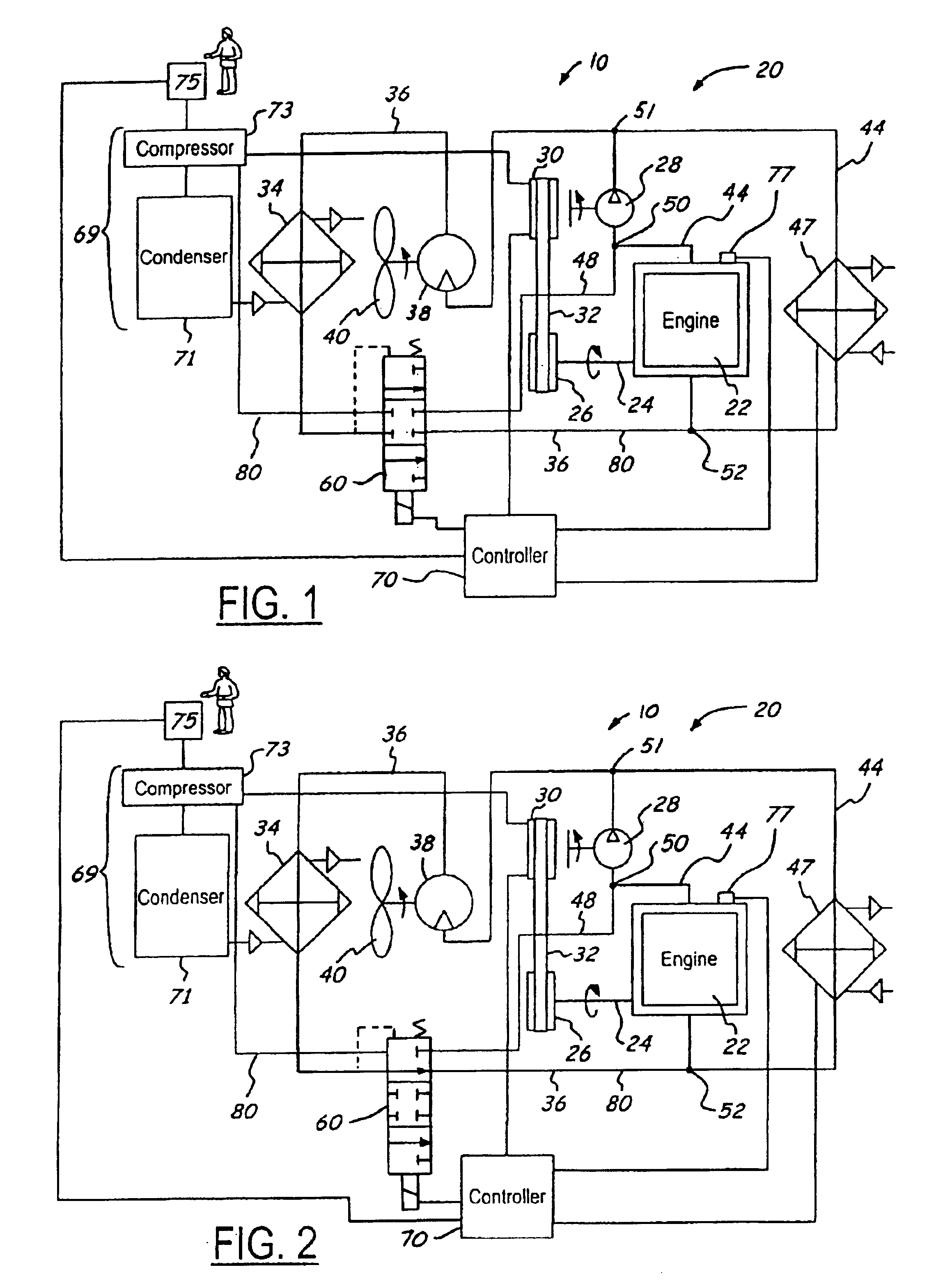
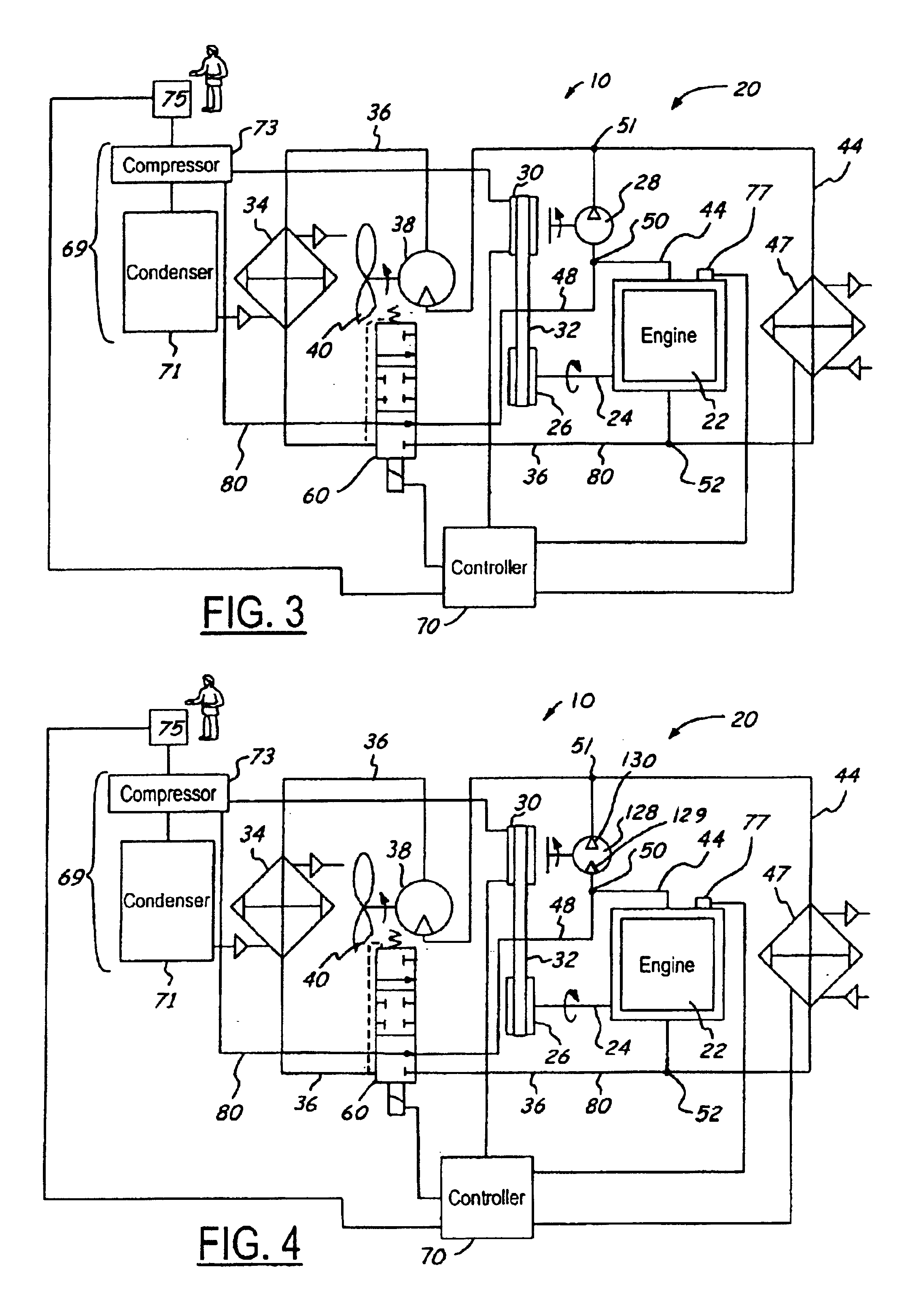
Referring now to FIGS. 1-3, a perspective view of a cooling system used to cool an engine 22 of a vehicle 10 in one preferred embodiment is generally designated as 20. The engine 22 has a crankshaft 24 coupled to a crankshaft pulley 26. The crankshaft pulley 26 is rotatably coupled to a water pump 28 via a pump control coupling 30, which is coupled to the crankshaft pulley 26 via a belt 32. The cooling system 20 also has a heater element 47 used to increase the temperature of the engine 22 as desired and to provide heated air to the passenger cabin of the vehicle as desired by a vehicle user75. The cooling system 20 also has an air-conditioning unit 69 providing cooling airflow to the passenger cabin as requested by the user 75.

The location of the user 75 relative to the heater element 47 and air conditioner 69, as shown in FIGS. 1-6 of the present invention, is merely for illustrative purpose only, and is not representative of their actual positioning within the vehicle 10.

The cool...


PUM


Abstract

The control of the coolant flow is accomplished through valving or by adjusting the pumping speed of a water pump and a water motor, or a combination of all three elements. During normal operation, where engine cooling is not required, the speed control coupling maintains a slow and constant water pump speed at all engine-operating speeds. The valve is maintained to stop coolant flow from entering the radiator while allowing coolant to flow through a heater. If engine cooling is required, the valve is actuated such that coolant is circulated to the engine and through the radiator. If air conditioning is required, the speed control coupling simply increases the water pump speed and the fan speed while the valve is set to bypass coolant flow to the engine. If air conditioning and engine cooling are required, the valve is actuated to allow coolant flow to the engine.

Description

TECHNICAL FIELDThe present invention relates generally to an engine cooling systems and more specifically to a coolant motor fan drive.BACKGROUND ARTGenerally, a water-cooling type engine of a vehicle includes a cooling system provided with a radiator and a flow control valve. The radiator is located in an engine coolant circuit for cooling the coolant. The flow control valve regulates the flow of the coolant that passes through the radiator. The flow control valve is controlled to change the coolant flow in the radiator (hereafter, “the radiator flow”). This adjusts the temperature of the coolant, which cools the engine.The flow control valve is fully closed to minimize the radiator flow when the coolant temperature is relatively low. In contrast, when the coolant temperature is relatively high, the flow control valve is fully opened to maximize the radiator flow. Otherwise, a feedback control procedure is performed to vary the opening size of the flow control valve (the radiator f...

Claims


Application Information

Patent Timeline
Patent Type & Authority Patents(United States)
IPC IPC(8): B60H1/32F01P7/04F01P5/10F01P7/00F01P5/02F01P5/00F01P5/04B60H1/00
CPCB60H1/00885F01P7/044F01P5/10F01P2070/08F01P2060/14
Inventor ROBB, NEIL E.
Owner BORGWARNER INC
Why Eureka
Try Eureka