[0020] The
amplification factor of an
amplifier circuit (amplification portion) is determined by a combination of resistors (resistive elements). Therefore, as in the case of the above-described determination of the
frequency band, selecting the
amplification factor by resistive elements of which the resistance value varies in response to the ambient temperature, makes it possible to cancel out the influence of variations in the sensor output and make temperature compensation.
[0022] As described above, the amplification factor of the
amplifier circuit (amplification portion) is determined by a combination of resistors (resistive elements). The filter portion is composed of
capacitor (capacitive element) and
resistor (
resistive element). Using the
resistive element, which is
common element between the amplification portion and filter portion, and an element of which the resistance values varies in response to the ambient temperature. In consequence, temperature compensation performance of the amplification portion and filter portion can be conveniently and collectively managed. Also, as using resistors having temperature dependence, it is improved in availability of components and productivity.
[0023] As resistive elements, it is preferably used thermistors. The
thermistor is also referred to as a “thermo-sensitive
resistor”, and it is a
resistor of which the resistance value significantly varies with the variation in temperature. The temperature coefficients of thermistors include positive one and negative one. The former corresponds to the case where the resistance value increases as the ambient temperature increases, while the latter corresponds to the case where the resistance value decreases as the ambient temperature increases. Also, some of the resistance values of thermistors linearly change with respect to temperature, and others of them exponentially change with respect to temperature. Thermistors that are more often utilized as detection sensors have better correlation between the temperature and the resistance value thereof, and hence such thermistors can be easily fitted to the characteristics of the filter portion and amplification portion.
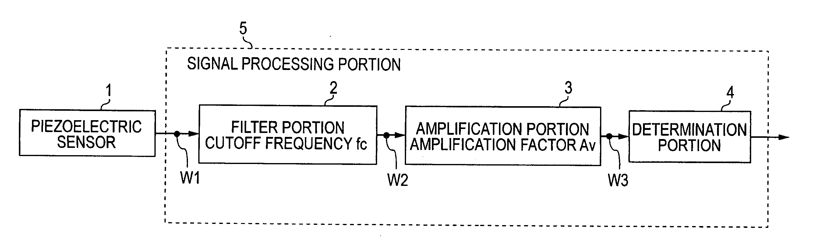
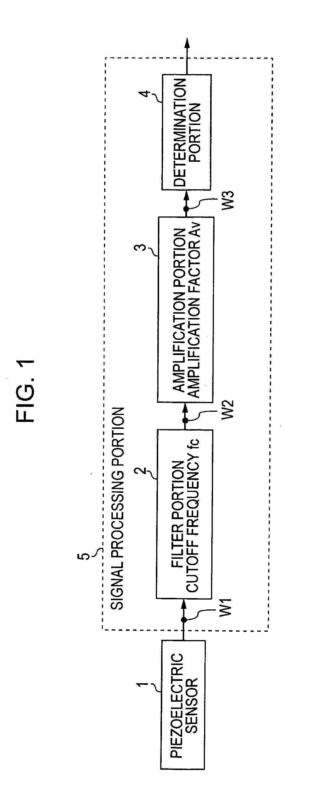
[0025] The
piezoelectric sensor is a sensor utilizing the electric polarization by the piezoelectric effect, and detects an applied external force, based on a frequency and a magnitude of
voltage of a
voltage signal generated by electric polarization. The
piezoelectric sensor has a simple structure, and is superior in
mass-productivity, as well as its signal circuit for
processing outputs is simple in constitution and easy to use. Furthermore, because the
piezoelectric sensor starts to generate a voltage from a time when an external force is weak, such as an initial stage of a pinching process, an
early detection is feasible. It is therefore possible to cope with the pinching before a force applied to the pinched object grow, so that the piezoelectric sensor is suitable to a sensor used for a pinching detection device. A substance having the piezoelectric effect of the piezoelectric sensor, such as a
crystal of
barium titanate exhibits pyroelectric property as well as piezoelectric effect, and is used also as a material of a
thermistor, which is a resistor of which the resistance value significantly varies with the variation in temperature. Hence, it is also possible to construct a sensor for detecting the external force due to pinching, and a temperature detecting element in a temperature compensating circuit for compensating for the temperature dependence of this sensor, using a substance having the same property, for each of the temperature detecting element and temperature compensating circuit.
[0027] According to this feature, since the piezoelectric sensor is provided into a
coaxial cable, it is easily formed a long figured sensor. Even the piezoelectric sensor can be installed along a bended door frame or door for a vehicle. At the time of arrangement also, the piezoelectric sensor is subjected to no influence of bending or pressure applied when installed, thus allowing a pinching detection device to be satisfactorily constructed.
[0028] When attempting to form the piezoelectric sensor as a
coaxial cable, typically, the piezoelectric material is constructed as a piezoelectric layer by combining resin or the like and piezoelectric
ceramic or the like. As a result, when the rigidity of the piezoelectric layer including resin varies due to the ambient temperature, the way of external force application to the piezoelectric sensor varies. Therefore, the output of the
coaxial cable shaped piezoelectric sensor easily varies in response to the variation in temperature. However, as described above, in the present invention, since the frequency band extracted by the filter portion and the amplification factor of the amplification portion are determined in response to the ambient temperature, it is possible to cancel out the temperature dependence to make good temperature compensation, and to inhibiting the above-described variation in the sensor output.

