Cold start fuel vapor enrichment

a fuel vapor enrichment and cold start technology, applied in the direction of electric control, combustion air/fuel air treatment, machines/engines, etc., can solve the problems of reducing engine stability, adversely affecting vehicle drivability, and also “cold” of the catalyst,

Inactive Publication Date: 2005-03-22
GM GLOBAL TECH OPERATIONS LLC
View PDF10 Cites 8 Cited by
  • Summary
  • Abstract
  • Description
  • Claims
  • Application Information

AI Technical Summary

Problems solved by technology

During an initial startup period after a long soak, the engine is still “cold” after starting and combustion of the gasoline is incomplete.
During the startup period, the catalytic converter is also “cold” and does not operate optimally.
However, the lean condition reduces engine stability and adversely impacts vehicle drivability.
However, the secondary air injection system increases cost and complexity of the engine control system and is only used during a short initial cold start period.

Method used


Image

  • Cold start fuel vapor enrichment
  • Cold start fuel vapor enrichment
  • Cold start fuel vapor enrichment

Examples


Embodiment Construction

The following description of the preferred embodiment is merely exemplary in nature and is in no way intended to limit the invention, its application, or uses. For purposes of clarity, the same reference numbers will be used in the drawings to identify similar elements.

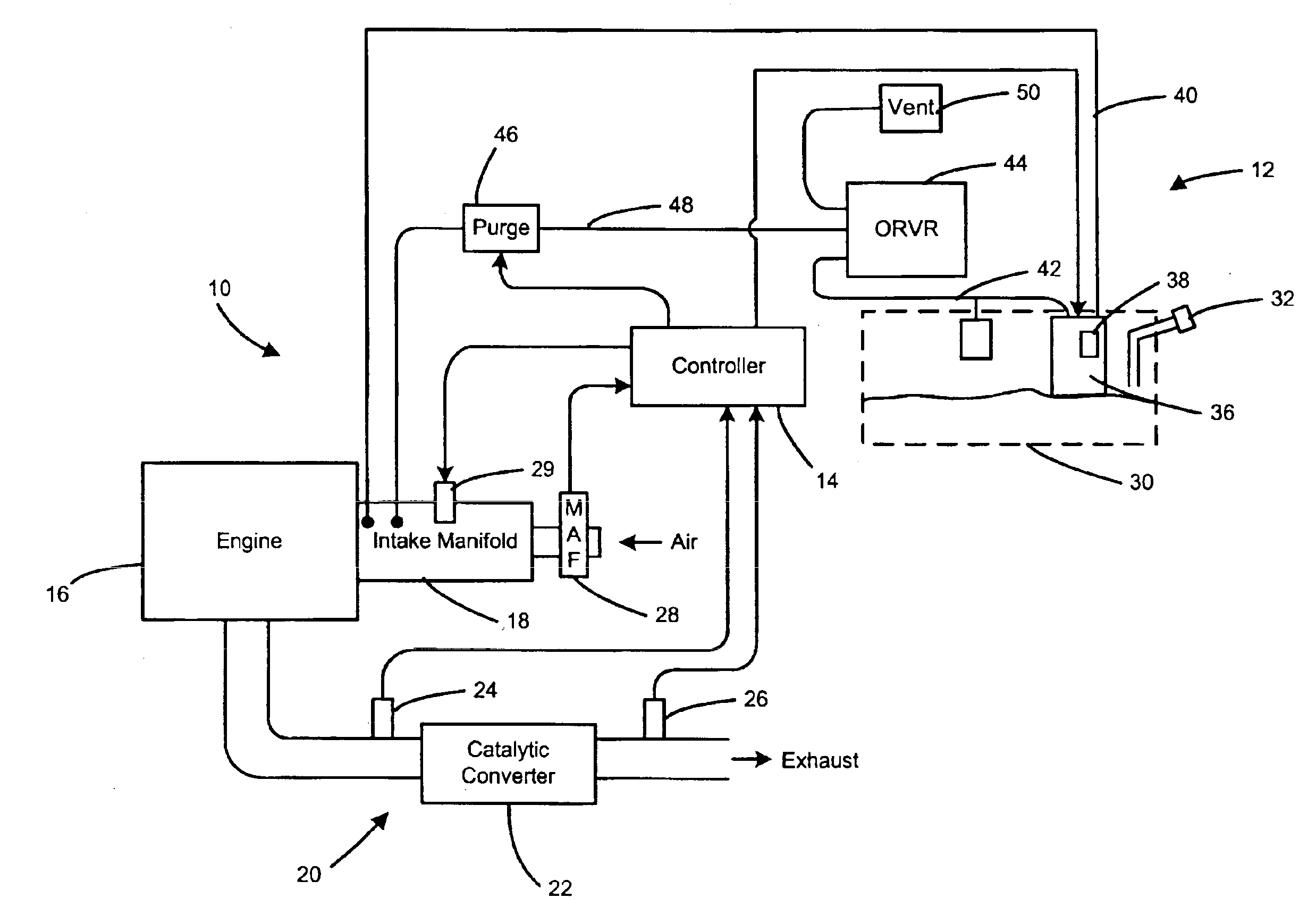
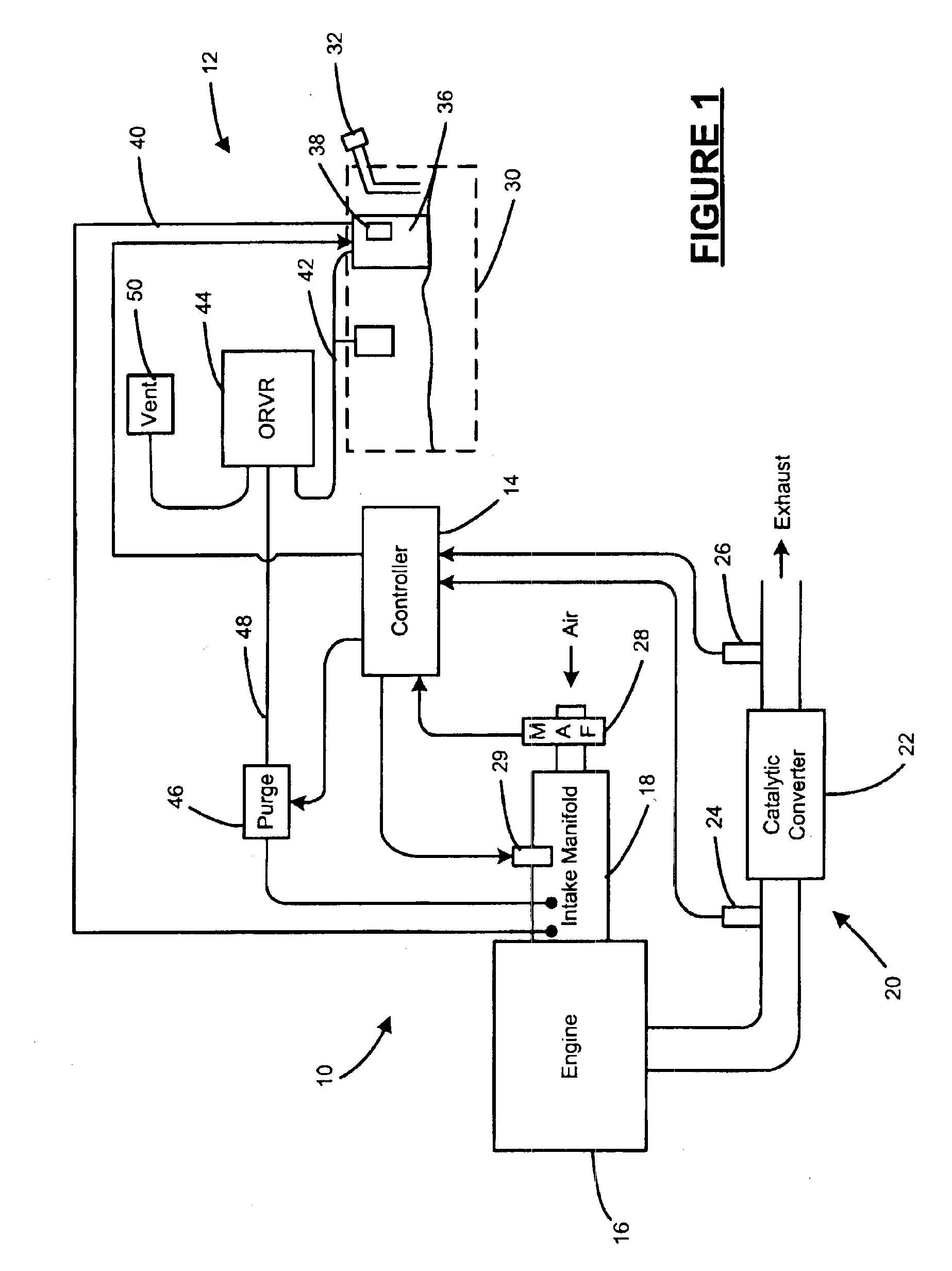
Referring to FIG. 1, an engine system 10 and a fuel system 12 are shown. One or more controllers 14 communicate with the engine and fuel systems 10, 12. The fuel system 12 selectively supplies liquid and / or vapor fuel to the engine system 10, as will be described in further detail below.

The engine system 10 includes an engine 16, an intake manifold 18, and an exhaust 20. Air and fuel are drawn into the engine 16 and combusted therein. Exhaust gases flow through the exhaust 20 and are treated in a catalytic converter 22. First and second O2 sensors 24 and 26 communicate with the controller 14 and provide exhaust A / F ratio signals to the controller 14. A mass air flow (MAF) sensor 28 is located within an air inlet and p...


PUM


Abstract

An engine system includes an engine, a fuel system that communicates with the engine, and a controller that communicates with the fuel system. The controller controls a first quantity of liquid fuel to the engine at a first A / F ratio and a second quantity of vapor fuel to the engine at a second A / F ratio during a predetermined period after start-up. The liquid and vapor fuel mixture has a third A / F ratio. The controller determines an available A / F ratio of vapor fuel within the fuel tank and performs a comparison with a target A / F ratio range. The second quantity is set to zero if the A / F ratio of the vapor fuel is outside of the target A / F ratio range. The controller adjusts the first and second quantities based on a comparison between an exhaust A / F ratio and a target exhaust A / F ratio.

Description

FIELD OF THE INVENTIONThe present invention relates to engine control systems, and more particularly to engine control systems that provide vapor enrichment of fuel flowing to an engine during cold start conditions.BACKGROUND OF THE INVENTIONDuring combustion, an internal combustion engine oxidizes gasoline and combines hydrogen (H2) and carbon (C) with air. Combustion creates chemical compounds such as carbon dioxide (CO2), water (H2O), carbon monoxide (CO), nitrogen oxides (NOx), unburned hydrocarbons (HC), sulfur oxides (SOx), and other compounds. During an initial startup period after a long soak, the engine is still “cold” after starting and combustion of the gasoline is incomplete. A catalytic converter treats exhaust gases from the engine. During the startup period, the catalytic converter is also “cold” and does not operate optimally.In one conventional approach, an engine controller commands a lean air / fuel (A / F) ratio and supplies a reduced mass of liquid fuel to the engin...

Claims


Application Information

Patent Timeline
IPC IPC(8): F02D41/00F02D41/06F02M25/08
CPCF02D41/0035F02D41/064F02D41/1458F02M25/08F02D2200/0414
Inventor AMENT, FRANK
Owner GM GLOBAL TECH OPERATIONS LLC
Why Eureka
Try Eureka