Small watercraft

a watercraft and small technology, applied in the field of small watercraft, can solve the problem of light deformation of the engine, and achieve the effect of lessening the variation in temperature and temperature distribution of the engin

Inactive Publication Date: 2005-03-22
KAWASAKI HEAVY IND LTD
View PDF6 Cites 14 Cited by
  • Summary
  • Abstract
  • Description
  • Claims
  • Application Information

AI Technical Summary

Benefits of technology

The present invention addresses the above-described condition, and an object of the present invention is to provide a small watercraft having an engine cooling system which can lessen variation in temperature and temperature distribution of an engine for the watercraft between the time when the engine is starting and when the watercraft is continuously driving with a throttle in a fully open or almost fully open position.
Preferably, the cooler may have fins protruding from the casing of the water jet pump into a heat exchange chamber provided in the cooler so as to allow the cooling water to flow therein. With this structure, the cooler easily achieves high heat exchange capability.

Problems solved by technology

This causes slight deformation of the engine.
In particular, in the case of an engine designed to minimize a clearance between a piston and a cylinder bore for the purpose of reducing lubricating oil consumption or a piston lap noise, slight deformation of the cylinder bore would lead to a noise or the like.

Method used


Image

  • Small watercraft
  • Small watercraft
  • Small watercraft

Examples


embodiment 1

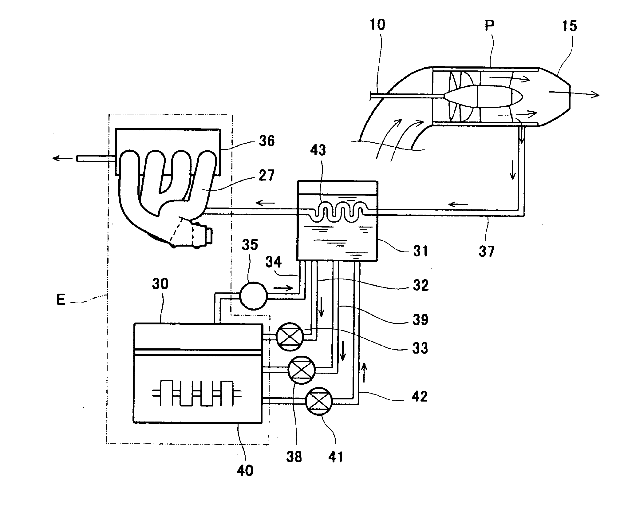
The water-jet propulsion personal watercraft according to an embodiment of the present invention has a cooling system schematically shown in FIG. 1. As shown in FIG. 1, an oil tank 31 is provided independently of the engine E. A low-temperature oil is pumped by an oil pump 33 to be delivered from the oil tank 31 into a cooling jacket inside a cylinder block 30 of the engine E through an oil pipe 32. The oil cools the cylinder block 30 and increases its temperature, and the resulting oil is returned into the oil tank 31 through an oil pipe 34. That is, a flow path of the oil is formed in a closed loop. The oil pipe 34 is provided with a thermostat valve 35 inside thereof to be adapted to open at a predetermined temperature or higher.

Meanwhile, low-temperature water from outside the watercraft is taken in as cooling water by the water jet pump P and is led into a cooling passage (cooling jacket) inside an exhaust manifold 27 through a cooling water supply line 37 and then into a cooli...

embodiment 2

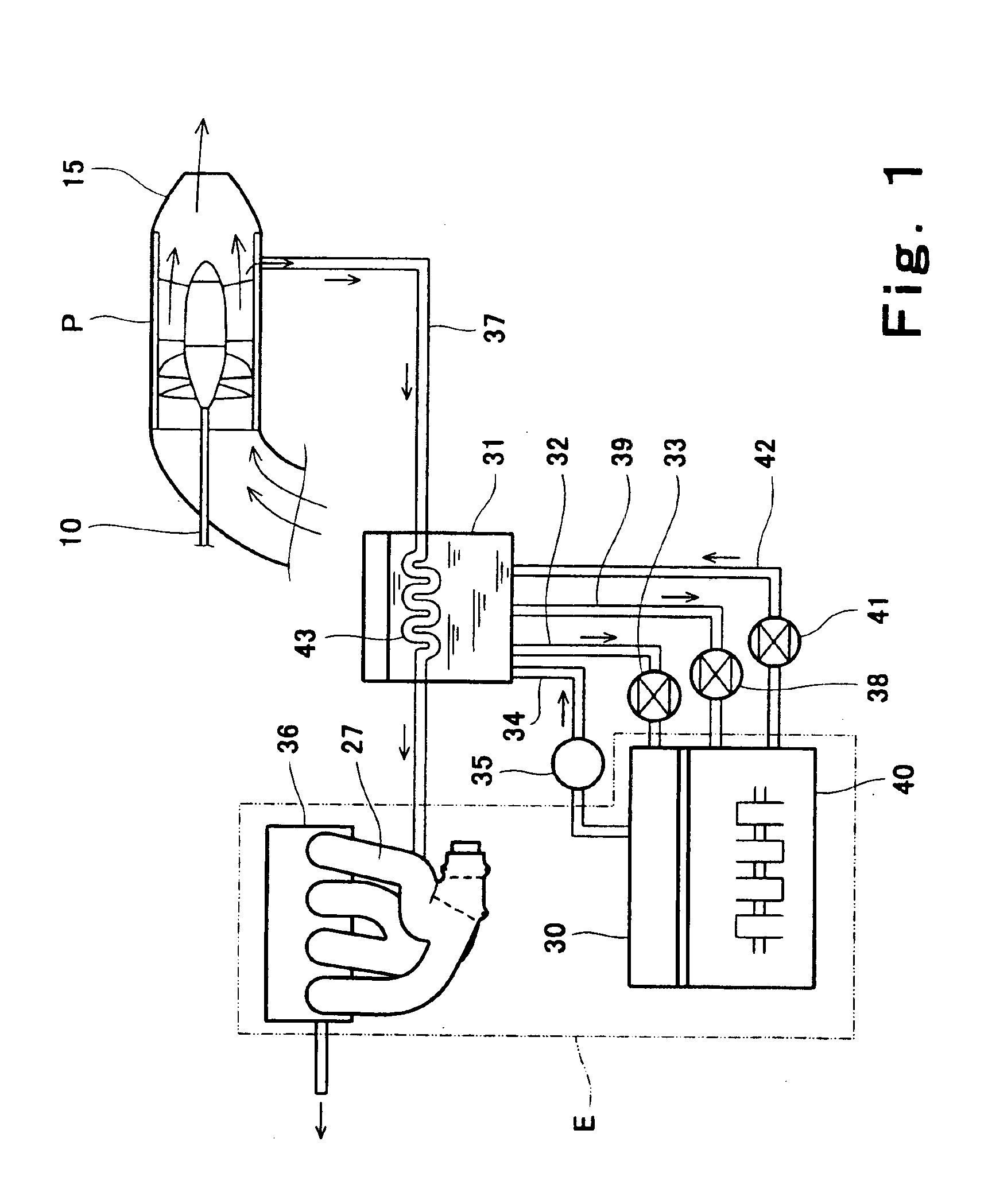
FIG. 2 shows another cooling system. In the system in FIG. 2, an oil cooler 53 is provided in the oil pipe 32 through which the oil is delivered from the oil tank 31 to the cooling jacket of the cylinder block 30 of the engine E by the oil pump 33.

FIGS. 5A-5C and 6A-6C show two examples of the oil cooler 53. An oil cooler 53A in FIGS. 5A-5C and an oil cooler 53B in FIGS. 6A-6C are respectively box-shaped and provided in contact with an outer peripheral wall of the pump casing 13 of the water jet pump P. Such a cooling structure advantageously utilizes cooling capability of the water jet pump P.

The oil cooler 53A in FIGS. 5A-5C is configured such that fins 54 for heat exchange protrude from the pump casing 13 to a center of a heat exchange chamber 55 of the oil cooler 53A. A connecting pipe 32A for connecting the oil pipe is connected to a bottom wall 56 of the heat exchange chamber 55 such that an end of the connecting pipe 32A on an inflow (entrance) side of the heat exchange chamb...

embodiment 3

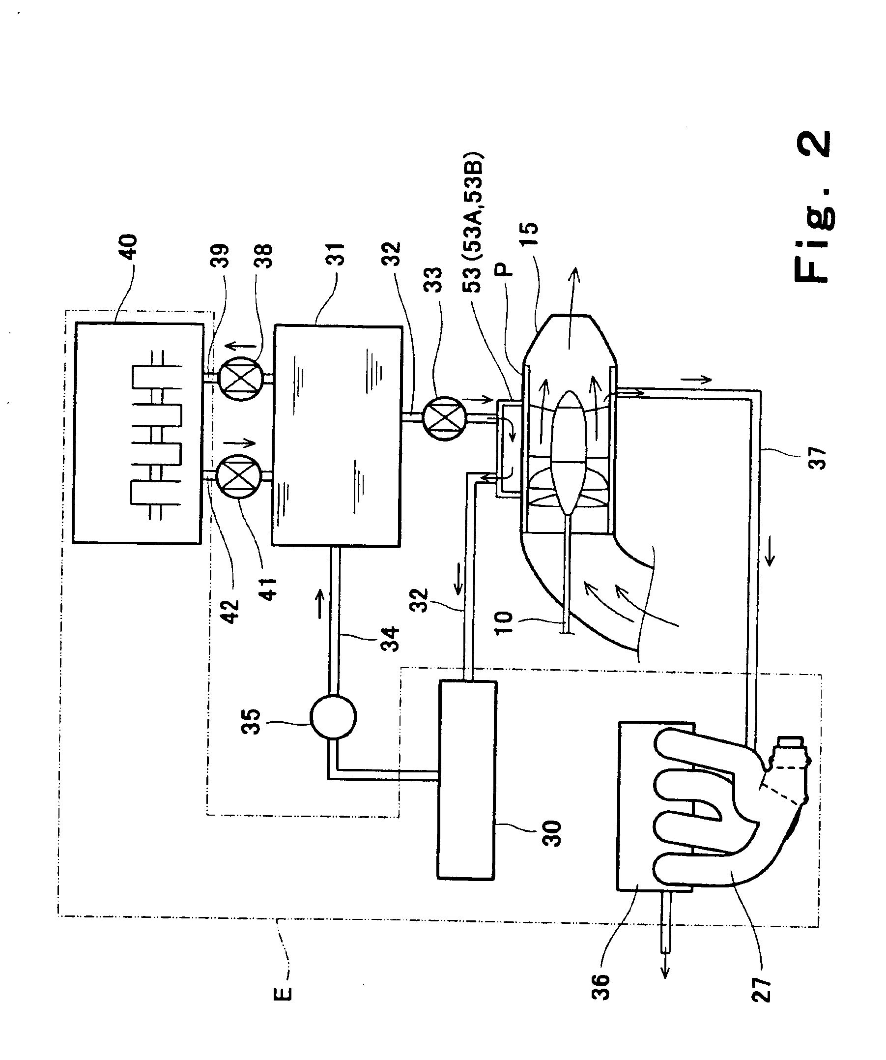
As shown in FIG. 3, cooling water (permanent coolant) may be used as a primary coolant for the cylinder block 30 of the engine E. In this cooling system, the cooling jacket of the cylinder block 30 is independently cooled. In this system, as in the second embodiment, the cooling water (permanent coolant) is cooled by a cooler 53 mounted on the outer peripheral wall (pump casing 13) of the water jet pump P. Therefore, this system effectively utilizes the cooling capability of the water jet pump P. This cooling system is identical to those in the first and second embodiments in that the pump 33 for circulating the coolant (in this embodiment, the cooling water) and the thermostat valve 35 for turning on / off circulation of the coolant are provided on the oil pipe 32 and the oil pipe 34, respectively. The cooler 53 may have any one of the structures in FIGS. 5A-5C and 6A-6C as in the first and second embodiments.

As in the first embodiment, the oil is fed from the oil tank 31 to the comp...


PUM


Abstract

Disclosed is a small watercraft having an engine cooling system which can lessen variation in temperature and temperature distribution of the engine between the time when the engine is starting and when the watercraft is continuously driving with a throttle in a fully open or almost fully open position. The small watercraft adapted to be propelled by a water jet pump driven by an engine, comprises: a first cooling system for cooling a cylinder block of the engine, the first cooling system having an indirect cooling structure; and a second cooling system for cooling an exhaust system, the second cooling system having a direct cooling structure.

Description

BACKGROUND OF THE INVENTION1. Field of the InventionThe present invention relates to a small watercraft such as a personal watercraft (PWC) which ejects water rearward and hydroplanes as the resulting reaction. More particularly, the present invention relates to a cooling system of an engine or the like of the small watercraft.2. Description of the Related ArtIn recent years, so-called water-jet propulsion personal watercraft, which are one type of small watercraft, have been widely used in leisure, sport, rescue activities, and the like. The water-jet propulsion personal watercraft is configured to have a water jet pump that pressurizes and accelerates water sucked from a water intake generally provided on a bottom surface of a hull and ejects it rearward from an outlet port. Thereby, the personal watercraft is propelled.In the water-jet propulsion personal watercraft, a steering nozzle provided behind the outlet port of the water jet pump is swung either to the right or to the lef...

Claims


Application Information

Patent Timeline
Patent Type & Authority Patents(United States)
IPC IPC(8): B63H11/00B63H21/00B63H21/14B63H11/10F01N3/04F01P3/20F01P3/02F01P3/00B63H11/08B63B35/73B63H21/38
CPCB63H21/14F01N3/046F01P3/207B63H11/10B63B2770/00Y02T10/20F01N2240/02F01P3/00F01P2003/005F01P2003/021F01P2003/024F01P2003/027F01P2050/06F01P2060/04F01P2060/16B63H21/24B63H21/383B63H21/386B63B34/10Y02T10/12
Inventor MATSUDA, YOSHIMOTO
Owner KAWASAKI HEAVY IND LTD
Why Eureka
Try Eureka