Fuel cell system with improved humidification system

Active Publication Date: 2005-03-22
TOSHIBA INT FUEL CELLS CORP +1
View PDF13 Cites 12 Cited by
  • Summary
  • Abstract
  • Description
  • Claims
  • Application Information

AI Technical Summary

Benefits of technology

A method is disclosed for operating a fuel cell power plant having a membrane electrode assembly (“MEA”) with an active area and a plate adjacent to the MEA. The plate is made with a porous material, and has a reactant channel and a coolant channel. The reactant channel delivers a reactant to the active area and is separated from the coolant channel by the porous material. The method includes flo

Problems solved by technology

A drawback to internal humidification stems from the difficulty in providing a uniform distribution of water in the CSA.
For example, inadequate control of the pressure differential between the coolant and reactant can result in a mal-distribution of water, which degrades cell performance.
If the coolant pressure is too low humidification can be insufficient, which increases internal ohmic resistance.
If the coolant pressure is too high, excess water can enter the gas passages and flood the electrodes.
Another difficulty with internal humidification is controlling the water distribution in the plane of the active area of the MEA.
If the coolant pressure is sufficient to humidify the upstream region of the active area, water may be excessive in the downst

Method used


Image

  • Fuel cell system with improved humidification system
  • Fuel cell system with improved humidification system
  • Fuel cell system with improved humidification system

Examples


Embodiment Construction

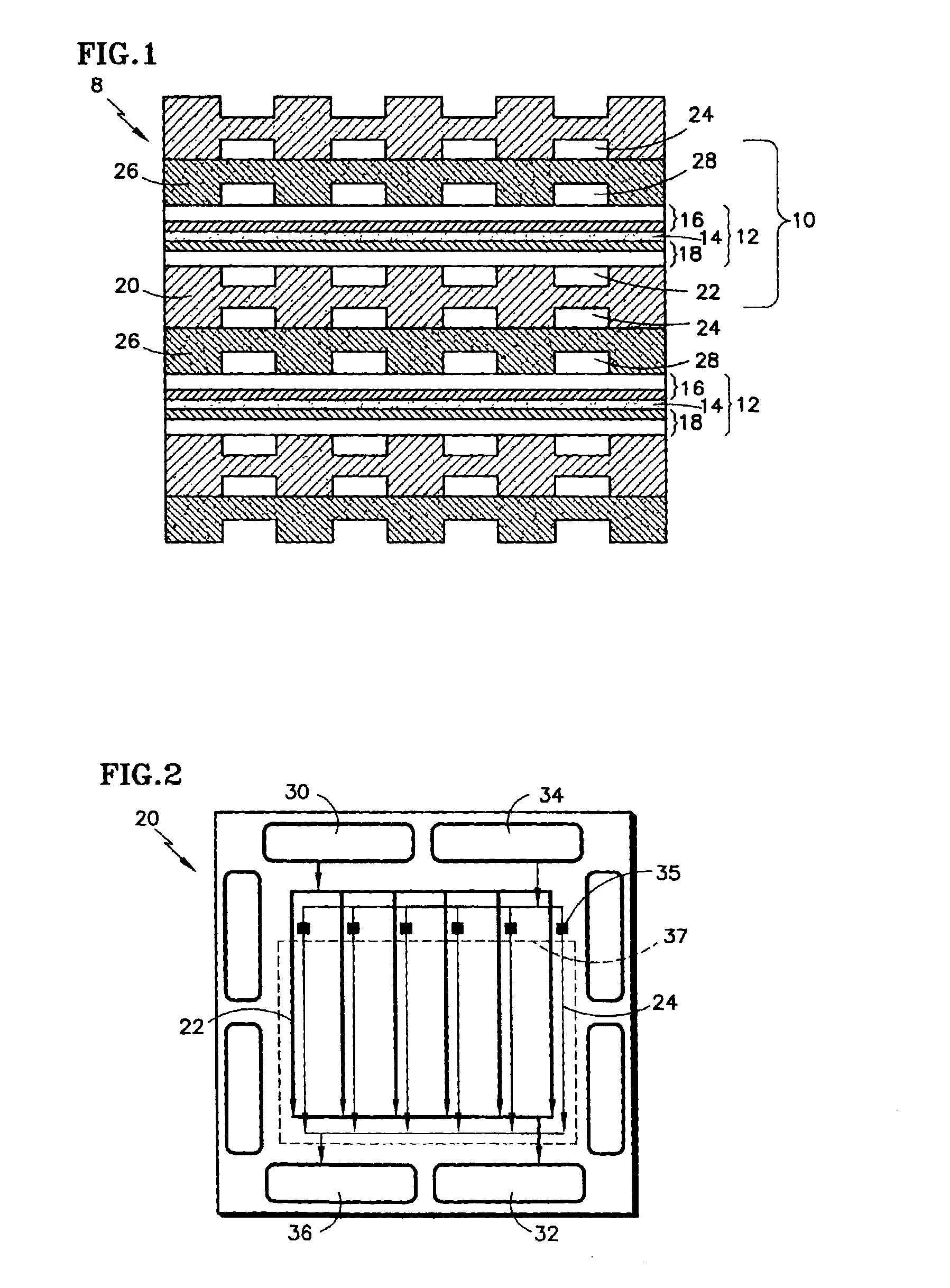
FIG. 1 shows a portion of a cell stack assembly (“CSA”) (8) having at least one fuel cell unit (10). The fuel cell unit can have a membrane electrode assembly (“MEA”) (12), a first or cathode side reactant distribution plate (20), and a second or anode side reactant distribution plate (26). The MEA has a proton exchange membrane (“PEM”) (14) between an anode electrode (16) and a cathode electrode (18). The electrodes can be of designs known to those skilled in the art, and may comprise one or more layers of material depending upon the needs of a specific fuel cell design. The first distribution plate (20) can be positioned adjacent the cathode (18), with oxidant flow passages (22) on a surface facing the cathode and coolant flow passages (24) located on the opposite surface of the plate. The second distribution plate (26) is positioned adjacent the anode (16), and can have fuel flow passages (28) on the surface facing the anode. The plate (26) can be made of a conductive, solid or p...


PUM


Abstract

A method for operating a fuel cell power plant. The fuel cell can include a reactant passage (22) with an upstream portion and a downstream portion for providing reactant to an electrode (16, 18), at least one liquid passage (24), and a plate (20) made from a porous material that is liquid permeable and conductive. The porous material separates the reactant passage and the liquid passage. A pressure profile is controlled to provide a positive pressure difference in the upstream portion and a negative pressure difference in the downstream portion. A positive pressure difference is one where the liquid pressure is higher than that of the reactant. A negative pressure difference is one where the liquid pressure is less than that of the reactant. The pressure profile can be used to provide enhanced humidification of the reactant in the upstream portion and effective liquid water removal in the downstream portion to maximize both the performance and the life of the fuel cell.

Description

TECHNICAL FIELDThe technical field is fuel cell power plants. More specifically, a fuel cell power plant having a humidification system with a controlled and adjustable pressure profile that simultaneously humidifies incoming reactant and removes excess liquid water from the reactant passages.BACKGROUND ARTFuel cell power plants are well known and may be used, for example, as power sources for electrical apparatus in space vehicles, power sources in automotive applications, and as stationary electricity generators for buildings. In a typical fuel cell power plant, multiple fuel cells are arranged together in a repeating fashion to form a cell stack assembly (“CSA”). Each individual fuel cell in the CSA typically includes an anode electrode and a cathode electrode separated by an electrolyte. A reactant fuel (e.g. hydrogen) is supplied to the anode, and a reactant oxidant (e.g. oxygen or air) is supplied to the cathode. The hydrogen electrochemically reacts at a catalyzed area of the...

Claims


Application Information

Patent Timeline
IPC IPC(8): H01M8/04H02J
CPCH01M8/04104H01M8/04186H01M8/04134Y02E60/50
Inventor SHIMOTORI, SOICHIROOGAMI, YASUJIPERRY, MICHAEL L.
Owner TOSHIBA INT FUEL CELLS CORP
Why Eureka
Try Eureka